


ZC706 Evaluation Board User Guide
60
UG954 (v1.5) September 10, 2015
Feature Descriptions
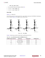
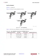
GPIO DIP Switch
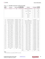
shows the GPIO DIP switch circuit.
lists the GPIO DIP switch connections to XC7Z045 AP SoC U1.
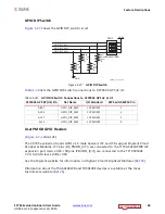
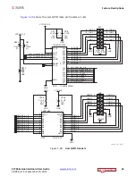
User PMOD GPIO Headers
[
, callout 26]
The ZC706 evaluation board GPIO 2 x 6 male headers J57 and J58 support Digilent Pmod
Peripheral Modules. J57 pins (IIC_PMOD_[0:7]) are connected to the TI TCA6416APWR I2C
expansion port device U16. J58 pins (PMOD1_[0:7]) are connected to the TI TXS0108E
3.3V-to-VADJ level-shifter U40.
See the Digilent website for information on Digilent Pmod Peripheral Modules
.
Information about the TCA641APWR and TXS0108E devices is available at the Texas
Instruments website
.
X-Ref Target - Figure 1-27
Figure 1-27:
GPIO DIP Switch
Table 1-30:
GPIO DIP Switch Connections to XC7Z045 AP SoC at U1
XC7Z045 AP S0C (U1) Pin
Net Name
I/O Standard
DIP Switch SW12 Pin
AB17
GPIO_DIP_SW0
LVCMOS25
1
AC16
GPIO_DIP_SW1
LVCMOS25
2
AC17
GPIO_DIP_SW2
LVCMOS25
3
AJ13
GPIO_DIP_SW3
LVCMOS25
4
UG954_c1_27_041113
SDA02H1SBD
SW12
VADJ
8
7
GPIO_DIP_SW0
GPIO_DIP_SW1
R70
4.7 k
Ω
0.1 W
5%
R71
4.7 k
Ω
0.1 W
5%
1
2
R68
4.7 k
Ω
0.1 W
5%
R69
4.7 k
Ω
0.1 W
5%
GND
GPIO_DIP_SW2
GPIO_DIP_SW3
6
5
3
4
1
2
1
2
1
2
1
2


