XICOY CG Meter 1.4 Скачать руководство пользователя страница 5


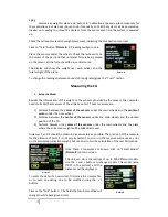
Click on the field you want to edit. 

 
A virtual keyboard will be shown, alphabetic if the field to be 
edited is the model name, numeric for the numeric fields. 
 
Use  the  “Del”  key  to  delete  the  characters  of  the  old  text 
displayed on the blue ribbon, enter the new text. Once done, 
then click on “OK”. 
 

Enter the distances on the other fields using same procedure, 
and select  if your plane  has  Tricycle  undercarriage or  Bicycle 

(Tail Dragging). 
 
Once all data entered, click on “Save” button. This data will be recorded in the memory of the 
unit. 
 
Finally click on SELECT button to record the selected model in the permanent memory. 
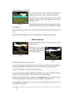


Measuring the CG 


Click  on  the  CG  button on  the  main  screen  to access  to the 
measured results. 
 
Depending  of  the  model 
type  selected,  the  displayed 
image  will  be  different,  but 
the data is the same. 


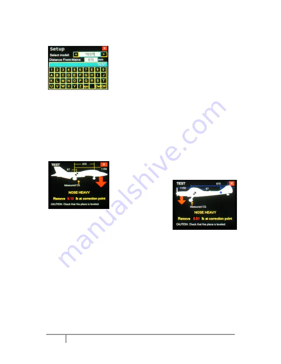
On top, left side, the model name is shown. 
 
On  top  of  the  drawing,  the  distances  set  in  the  setup  screen  are  shown.  The  CG  symbol  is 
placed on the drawing at scale distance, and the correction point is shown as a BLUE dot. 
 
Under the drawing, the results of the measure are shown. 
 
The  current  measured  location  is  displayed;  graphically  you  can  see  its  location  relative  to 
desired CG and numerically as the current distance from main landing gear. 
 
A RED arrow indicates the “Heavy” side (Nose/Tail) (

Picture 10

). The amount of the correction 

to be placed / removed from the correction point is displayed on the bottom line. 
 
The  measures  are  updated  in  real  time,  so  you  can  move  equipment,  add  weight,  etc.  and 
immediately see the results. 
 

Picture 9 

Picture 10 

Picture 11 

Содержание CG Meter 1.4

Страница 1: ...au 18 08360 Canet de Mar Barcelona Catalonia Spain E mail sales xicoy com 34 93 794 27 74 web www xicoy com Xicoy WEEE register number ES004749 DE 36558999 Copyright 2015 Xicoy Electronica SL All Rights Reserved Manual contents design Gaspar Espiell V1 4 ...

Страница 2: ...b weight standard model or up to 100Kg 220lb on the HD model By replacing the weight sensor by angle sensors the system can be used to adjust the travel of control surfaces and to measure the different relevant angles in an aero plane The display unit can store the settings of up to 100 different models and can save recover the data on a uSD card not supplied Measuring CG and Weight The system con...

Страница 3: ...ortant to check and calibrate the sensors especially if they have got mechanical stress like transport or shock if the temperature is significantly different since last calibration or at least once per year After power on leave the system to stabilize for at least 5 minutes Then touch the weight button and next touch the Tare button All 3 readings should display zero Then place a known weight on e...

Страница 4: ...se measures are 1 Distance between the center of the sensors under the main wheels and the center of sensor under the nose wheel 2 Distance between the center of the sensors under the main wheels and the desired position of the CG 3 Distance between the center of the sensors under the main wheels and the place where the correction weight will be added removed Distances 1 and 2 should be measured a...

Страница 5: ...ess to the measured results Depending of the model type selected the displayed image will be different but the data is the same On top left side the model name is shown On top of the drawing the distances set in the setup screen are shown The CG symbol is placed on the drawing at scale distance and the correction point is shown as a BLUE dot Under the drawing the results of the measure are shown T...

Страница 6: ...sitions marked in BLUE lines The current position line is YELLOW in color when the position of the surface is between minimum and maximum Picture 12 The color will change to GREEN when the deflection is exactly as desired 0 5º If the deflection is excessive then the line color changes to RED Entering the data of the surfaces The unit accepts the data in either Distance or in Degrees Usually the ma...

Страница 7: ...e accordingly its position turning to GREEN in color when in correct position at full deflection The Side Buttons allow selecting the reference for the measurements Five options are offered Picture 17 1 Ground Absolute The 3 sensors work independently and the zero is absolute factory calibrated like a bubble level zero degrees will be displayed when the sensor is absolutely parallel to ground 2 Gr...

Страница 8: ...ration this button provides access to the calibration procedure CAUTION The calibration data from factory will be lost Picture 19 Do not calibrate a sensor if you don t have a precision reference weight of at least 1kg The sensors store the calibration values in the sensor memory In order to have access to this memory by the display module the sensor to be calibrated should be connected to input 1...

Страница 9: ... instead it must be taken to a suitable specialist disposal system In the countries of the EU European Union electrical equipment must not be discarded via the normal domestic refuse system WEEE Waste of Electrical and Electronic Equipment directive 2002 96 EG You can take unwanted equipment to your nearest local authority waste collection point or recycling centre There the equipment will be disp...

Отзывы: