background image

- 8 -

  XFX Motherboard Series                                                                                   User Guide

2.3 Installation of the CPU and CPU Cooler

    Before installing the CPU, please comply with the following conditions:
    1. Please make sure that the mainboard supports the CPU.
    2. Please take note of the one indented corner of the CPU. If you install the CPU in the wrong     
       direction, the CPU will not insert properly. If this occurs, please change the insert direction      
       of the CPU.
    3. Please add an even layer of heat sink paste between the CPU and CPU cooler.
    4. Please make sure the CPU cooler is installed on the CPU prior to system use, otherwise 
        overheating and permanent damage of the CPU may occur.
    5. Please set the CPU host frequency in accordance with the processor specifi cations. It is not 
        recommended that the system bus frequency be set beyond hardware specifi cations since 
        it does not meet the required standards for the peripherals. If you wish to set the frequen-     
        cy beyond the proper specifi cations, please do so according to your hardware     
        specifi cations including the CPU, graphics card, memory, hard drive, etc.


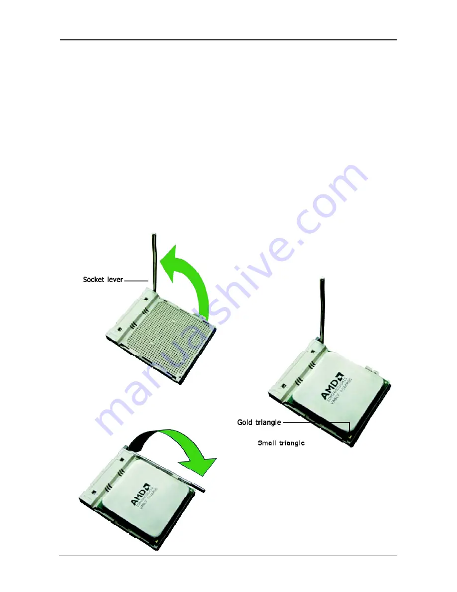
2.3.1 Installation of the CPU

1. Unlock the socket by pressing the 
   lever sideways, then lift it up to a 90

o

.

2. Position the CPU above the socket such 
    that the CPU corner with the gold 
    triangle matches the socket corner with 
    a small triangle.
3. Carefully insert the CPU into the socket 
    until it fi ts place.

4. When the CPU is in place, push down 
   the socket lever to secure the CPU. 
   The lever clicks on the side tab to 
   indicate that it is locked.

Figure 1

Figure 2

Figure 3

Содержание GeForce 8100 (MI-A78V-8109)

Страница 1: ...XFX Motherboard Series GeForce 8300 MI A78U 8309 GeForce 8200 MI A78S 8209 GeForce 8100 MI A78V 8109 AMD Socket AM2 Processor Motherboards User Guide...

Страница 2: ...p 11 3 1 Checking Jumper Settings 11 3 2 CMOS Memory Clearing Header 11 3 3 Keyboard Power Function JKB 11 3 4 FAN Power Connectors 12 3 5 Front Panel Switches Indicators Headers 12 3 6 Additional USB...

Страница 3: ...n 1 1 Package Checklist HDD Cable X 1 Rear I O Panel X 1 Quick Installation Guide X 1 Driver Utility CD X 1 Serial ATA Power Cable X 1 SATA Single Cable X 1 FDD Cable X 1 The items listed above are fo...

Страница 4: ...rated Ports 1 x PS 2 Keyboard port 1 x PS 2 Mouse Port 1 x DVI port 1 x Debug LED Optional 1 x HDMI port 1 x VGA port 1 x RJ45 port 10 x USB 2 0 ports USB 1 1 is compliant 6 x SATA ports by BGA Maximu...

Страница 5: ...5 XFX Motherboard Series User Guide 1 3 Mainboard Layout This picture is only for reference...

Страница 6: ...other side can insert SATA1 SATA2 SATA3 SATA4 USB Connects to USB devices such as scanner digital speakers monitor mouse keyboard hub digital camera joystick etc LAN Connects to Local Area Network AUD...

Страница 7: ...assis If the holes line up and there are screw holes you can attach the board with studs If the holes line up and there are only slots you can only attach with spacers Take the tip of the spacers and...

Страница 8: ...quency in accordance with the processor specifications It is not recommended that the system bus frequency be set beyond hardware specifications since it does not meet the required standards for the p...

Страница 9: ...ts connectors 4 Align the notch key on the module with the rib on the slot 5 Firmly press the module into the slots until the ejector tabs at both sides of the slot automatically snap into the mountin...

Страница 10: ...slot PCIE1 Install PCI Express X16 graphics card into slot PCIE2 Install PCI card into slots PCI1 or PCI2 Each of the IDE port connects up to two IDE drives at Ultra ATA 133 100 66 33 mode by one 40...

Страница 11: ...nd have it reconfigured to the default values stored in BIOS Pins 1 and 2 shorted Default Normal operation Pins 2 and 3 shorted Clear CMOS memory The button of CMOS_BT1 on back panel if press this but...

Страница 12: ...RESET Reset Control This connector connects to the case mounted reset switch for rebooting your computer without having to turn off your power switch This is a preferred method of rebooting in order...

Страница 13: ...CC 2 VCC 3 Data 0 4 Data 0 5 Data 0 6 Data 0 7 Ground 8 Ground 9 No Pin 10 NC HD Audio Pin No Definition 1 PORT1L 2 AGND 3 PORT1R 4 NC 5 PORT2R 6 SENSE1 7 SENSE 8 No Pin 9 PORT2L 10 SENSE2 3 6 Additio...

Страница 14: ...he Pin1 2 be shorted DVI has function of display Onboard VGA also can dispaly at the same time If the Pin2 3 be shorted HDMI has function of display Onboard VGA also can dispaly at the same time Pin N...

Страница 15: ...found on digital audio equipment such as a DAT Digital Audio Tape machine or audio processing device It allows the transfer of audio from one file to another without the conversion to and from an ana...

Страница 16: ...g special features on or off etc 3 Enhancing your computer s behavior For example speeding up performance by turning on shadowing or cache 4 2 To Run BIOS Setup First access BIOS setup menu by pressin...

Страница 17: ...on from the options and set the IDE boot order or set it as IDE Master Slave within them Floppy Configuration Click Press Enter key to enter its submenu it will be display floppy configuration and thi...

Страница 18: ...ft or right to select Screens Move cursor up or down to select items PU PD To Change option for the selected items Enter To bring up the selected screen ESC Main Menu Quit and not save changes into CM...

Страница 19: ...rong values in below sections may cause system to malfunction CPU Configuration Chipset Onboard Devices PCIPnP v02 61 C Copyright 1985 2006 American Megatrends Inc BIOS SETUP UTILITY Advanced CPU Conf...

Страница 20: ...function correctly Optional Disabled Enabled Chipset Click Press Enter key to enter its submenu that can select primary graphics adapter from optional items or set Internal VGA or External VGA CARD t...

Страница 21: ...submenu it will be display specifies the boot device priority sequence from available removable drives BIOS SETUP UTILITY Main Advanced Boot Security Power JUSTw00t Exit Boot Settings Configure Setti...

Страница 22: ...ess Esc to abort the selection BIOS SETUP UTILITY Main Advanced Boot Security Power JUSTw00t Exit Security Settings Install or Change the password Select Screen Select Item Enter Change F1 General Hel...

Страница 23: ...tion templates PC Health Click Press Enter key to enter its submenu it will be display hardware health configuration including System temperature CPU temperature FAN speed and all kinds of voltages BI...

Страница 24: ...en Select Item Enter Go to Sub Screen F1 General Help Load Optimal Defaults Load Failsafe Defaults Save configuration changes and exit setup Ok Cancel Ok Discard Changes and Exit Highlight this item a...

Страница 25: ...that option and then press F9 BIOS SETUP UTILITY Main Advanced Boot Security Power JUSTw00t Exit Exit Options Discards changes done so far to any of the setup questions F7 key can be used for this op...

Страница 26: ...in getting your system working properly again If you only want to install fail safe defaults for a specific option select and display that option and then press F8 BIOS SETUP UTILITY Main Advanced Bo...

Отзывы: