


10/00
4-162
Phaser 790/DocuColor 2006
ADJ 8.1, ADJ 9.1
Initial Issue
Repairs and Adjustments
Adjustment
1.
Calculate the difference between the average measured value and the nominal values as
displayed in the Table 1.
2.
Calculate the required adjustment value, allowing 1 unit increment to equal 0.17 mm of
change in top-to-bottom registration, or 0.50 mm of change in side-to-side registration.
3.
Prepare to adjust the printer registration.
a.
Enter the Diagnostic Mode (IOT) (GP 1).
b.
Press the Menu button until IOT PARAM SET is displayed.
c.
Press the Item Enter button.
d.
Press the Up Arrow or Down Arrow button until CTRL VAL SET is displayed, then
press the Item Enter button.
e.
Using the Up Arrow and Down Arrow buttons, select the Menu Number from the
Table 2.
f.
Press the Item Enter button to display the current value of that parameter.
g.
Using the Up Arrow and Down Arrow buttons, change the value as required.
h.
Press the Item Enter button to write the new value.
i.
Scroll the menu until DIAG EXIT is displayed, then press the Item Enter button.
j.
Wait until the message PLEASE POWER OFF is displayed and then switch off and
switch on the power.
4.
Perform the check again.
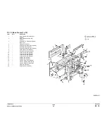
ADJ 9.1 Developer Spacing
Purpose
The purpose is to ensure that the Developer Housing is at the correct distance from the Copy/
Print Cartridge.
Check
WARNING
To avoid personal injury or shock, do not perform repair activities with the power switch
on or electrical power applied to the machine.
1.
Switch off the machine power and disconnect the machine Power Cord.
2.
Remove the Top Cover Assembly (REP 14.4).
3.
Release the Rotary Latch. Turn the Rotary Frame clockwise until the magnetic roll of the
target Developer Housing is at the top. Continue to turn until the Rotary Latch catches in
the notch of the Rotary Frame.
CAUTION
Do not touch the surface (surface around circumference) of the white tracking roll with your fin-
gers while performing the following step. If you accidentally touch the surface of the tracking
roll with your fingers or if oily substances get on the surface, wipe the roll clean with a clean
cloth.
4.
Clean the White Tracking Roll in front of the target Developer Assembly (in front of the
Magnetic Roll) with a clean cloth (Figure 1).
5.
Make a mark on the White Tracking Roll, at the edge of the White Seal, in front of the tar-
get Developer Assembly (in front of the Magnetic Roll).
If a mark already exists on the White Tracking Roll, rotate the roll to align the mark with
the edge of the White Seal (Figure 1).
CAUTION
Turn the Rotary Frame as slowly as possible while performing the following step. Turning the
Rotary Frame too fast will produce a discrepancy in the amount of position change, thus mak-
ing it impossible to get an accurate reading. Visually inspect to make sure the black drum
flange and tracking roll touch each other while turning.
If you do not raise the lever of the Rotary Latch in the following step, the lever and tracking roll
will touch. This will allow the tracking roll to turn and you will not be able to accurately deter-
mine the amount of position change.
NOTE: The tracking roll is rotated when the black drum flange and tracking roll touch in the fol-
lowing step of the procedure.
6.
Release the Rotary Latch which prevents the Developer Housing from turning. Turn the
Rotary Frame as slowly as possible 360 degrees (clockwise). This will allow you to mea-
sure how much the position has changed by how far the mark has moved from the edge
of the White Seal.
7.
Check the Developer Spacing (Figure 1).
Table 2 Printer Registration Items for the Parameters
Menu No. Function
Default
Value
Maximum
Value
Minimum
Value
Unit
11
Side-To-Side Registration 201 128 127
0.10 mm
16
Top-To-Bottom (Tray 1)
30
64
0
0.17 mm
17
Top-To-Bottom (Tray 2)
37
64
0
0.17 mm
18
Top-To-Bottom (Tray 3)
35
64
0
0.17 mm
19
Top-To-Bottom (Bypass Tray)
28
64
0
0.17 mm
1A
Top-To-Bottom (Duplex Tray)
17
64
0
0.17 mm
Содержание Phaser 790
Страница 4: ...10 00 ii Phaser 790 DocuColor 2006 Initial Issue Introduction...
Страница 10: ...10 00 1 2 Phaser 790 DocuColor 2006 Initial Issue Service Call Procedures...
Страница 14: ...10 00 1 6 Phaser 790 DocuColor 2006 Cleaning Procedures Final Actions Initial Issue Service Call Procedures...
Страница 18: ...10 00 2 4 Phaser 790 DocuColor 2006 Fault Message RAP Cross Reference Initial Issue Status Indicator RAPs...
Страница 46: ...10 00 2 32 Phaser 790 DocuColor 2006 002 702 Initial Issue Status Indicator RAPs...
Страница 80: ...10 00 2 66 Phaser 790 DocuColor 2006 005 704 Initial Issue Status Indicator RAPs...
Страница 100: ...10 00 2 86 Phaser 790 DocuColor 2006 007 341 Initial Issue Status Indicator RAPs Figure 1 007 341 RAP Circuit Diagram...
Страница 102: ...10 00 2 88 Phaser 790 DocuColor 2006 007 700 Initial Issue Status Indicator RAPs Figure 1 007 700 RAP Circuit Diagram...
Страница 104: ...10 00 2 90 Phaser 790 DocuColor 2006 007 701 Initial Issue Status Indicator RAPs Figure 1 007 701 RAP Circuit Diagram...
Страница 106: ...10 00 2 92 Phaser 790 DocuColor 2006 007 702 Initial Issue Status Indicator RAPs Figure 1 007 702 RAP Circuit Diagram...
Страница 108: ...10 00 2 94 Phaser 790 DocuColor 2006 007 703 Initial Issue Status Indicator RAPs Figure 1 007 703 RAP Circuit Diagram...
Страница 110: ...10 00 2 96 Phaser 790 DocuColor 2006 007 704 Initial Issue Status Indicator RAPs Figure 1 007 704 RAP Circuit Diagram...
Страница 112: ...10 00 2 98 Phaser 790 DocuColor 2006 007 705 Initial Issue Status Indicator RAPs Figure 1 007 705 RAP Circuit Diagram...
Страница 114: ...10 00 2 100 Phaser 790 DocuColor 2006 007 706 Initial Issue Status Indicator RAPs Figure 1 007 706 RAP Circuit Diagram...
Страница 117: ...10 00 2 103 Phaser 790 DocuColor 2006 007 708 Status Indicator RAPs Initial Issue Figure 1 007 708 RAP Circuit Diagram...
Страница 125: ...10 00 2 111 Phaser 790 DocuColor 2006 007 711 Status Indicator RAPs Initial Issue Figure 1 007 711 RAP Circuit Diagram...
Страница 127: ...10 00 2 113 Phaser 790 DocuColor 2006 007 712 Status Indicator RAPs Initial Issue Figure 1 007 712 RAP Circuit Diagram...
Страница 129: ...10 00 2 115 Phaser 790 DocuColor 2006 007 713 Status Indicator RAPs Initial Issue Figure 1 007 713 RAP Circuit Diagram...
Страница 130: ...10 00 2 116 Phaser 790 DocuColor 2006 007 713 Initial Issue Status Indicator RAPs...
Страница 138: ...10 00 2 124 Phaser 790 DocuColor 2006 008 702 Initial Issue Status Indicator RAPs Figure 1 008 702 RAP Circuit Diagram...
Страница 140: ...10 00 2 126 Phaser 790 DocuColor 2006 008 703 Initial Issue Status Indicator RAPs Figure 1 008 703 RAP Circuit Diagram...
Страница 145: ...10 00 2 131 Phaser 790 DocuColor 2006 008 705 Status Indicator RAPs Initial Issue Figure 1 008 705 RAP Circuit Diagram...
Страница 147: ...10 00 2 133 Phaser 790 DocuColor 2006 008 706 Status Indicator RAPs Initial Issue Figure 1 008 706 RAP Circuit Diagram...
Страница 149: ...10 00 2 135 Phaser 790 DocuColor 2006 008 707 Status Indicator RAPs Initial Issue Figure 1 008 707 RAP Circuit Diagram...
Страница 150: ...10 00 2 136 Phaser 790 DocuColor 2006 008 707 Initial Issue Status Indicator RAPs...
Страница 152: ...10 00 2 138 Phaser 790 DocuColor 2006 009 321 Initial Issue Status Indicator RAPs Figure 1 009 321 RAP Circuit Diagram...
Страница 154: ...10 00 2 140 Phaser 790 DocuColor 2006 009 323 Initial Issue Status Indicator RAPs Figure 1 009 323 RAP Circuit Diagram...
Страница 156: ...10 00 2 142 Phaser 790 DocuColor 2006 009 326 Initial Issue Status Indicator RAPs Figure 1 009 326 RAP Circuit Diagram...
Страница 158: ...10 00 2 144 Phaser 790 DocuColor 2006 009 340 Initial Issue Status Indicator RAPs Figure 1 009 340 RAP Circuit Diagram...
Страница 160: ...10 00 2 146 Phaser 790 DocuColor 2006 009 341 Initial Issue Status Indicator RAPs Figure 1 009 341 RAP Circuit Diagram...
Страница 162: ...10 00 2 148 Phaser 790 DocuColor 2006 009 342 Initial Issue Status Indicator RAPs Figure 1 009 342 RAP Circuit Diagram...
Страница 165: ...10 00 2 151 Phaser 790 DocuColor 2006 009 358 Status Indicator RAPs Initial Issue Figure 1 009 358 RAP Circuit Diagram...
Страница 167: ...10 00 2 153 Phaser 790 DocuColor 2006 009 359 Status Indicator RAPs Initial Issue Figure 1 009 359 RAP Circuit Diagram...
Страница 169: ...10 00 2 155 Phaser 790 DocuColor 2006 009 360 Status Indicator RAPs Initial Issue Figure 1 009 360 RAP Circuit Diagram...
Страница 173: ...10 00 2 159 Phaser 790 DocuColor 2006 009 701 Status Indicator RAPs Initial Issue Figure 1 009 701 RAP Circuit Diagram...
Страница 175: ...10 00 2 161 Phaser 790 DocuColor 2006 009 702 Status Indicator RAPs Initial Issue Figure 1 009 702 RAP Circuit Diagram...
Страница 177: ...10 00 2 163 Phaser 790 DocuColor 2006 009 703 Status Indicator RAPs Initial Issue Figure 1 009 703 RAP Circuit Diagram...
Страница 179: ...10 00 2 165 Phaser 790 DocuColor 2006 009 704 Status Indicator RAPs Initial Issue Figure 1 009 704 RAP Circuit Diagram...
Страница 180: ...10 00 2 166 Phaser 790 DocuColor 2006 009 704 Initial Issue Status Indicator RAPs...
Страница 185: ...10 00 2 171 Phaser 790 DocuColor 2006 010 354 Status Indicator RAPs Initial Issue Figure 1 010 354 RAP Circuit Diagram...
Страница 187: ...10 00 2 173 Phaser 790 DocuColor 2006 010 355 Status Indicator RAPs Initial Issue Figure 1 010 355 RAP Circuit Diagram...
Страница 189: ...10 00 2 175 Phaser 790 DocuColor 2006 010 358 Status Indicator RAPs Initial Issue Figure 1 010 358 RAP Circuit Diagram...
Страница 191: ...10 00 2 177 Phaser 790 DocuColor 2006 010 359 Status Indicator RAPs Initial Issue Figure 1 010 359 RAP Circuit Diagram...
Страница 193: ...10 00 2 179 Phaser 790 DocuColor 2006 010 700 Status Indicator RAPs Initial Issue...
Страница 195: ...10 00 2 181 Phaser 790 DocuColor 2006 010 701 Status Indicator RAPs Initial Issue Figure 1 010 701 RAP Circuit Diagram...
Страница 197: ...10 00 2 183 Phaser 790 DocuColor 2006 010 702 Status Indicator RAPs Initial Issue Figure 1 010 702 RAP Circuit Diagram...
Страница 199: ...10 00 2 185 Phaser 790 DocuColor 2006 010 703 Status Indicator RAPs Initial Issue Figure 1 010 703 RAP Circuit Diagram...
Страница 201: ...10 00 2 187 Phaser 790 DocuColor 2006 010 704 Status Indicator RAPs Initial Issue Figure 1 010 704 RAP Circuit Diagram...
Страница 203: ...10 00 2 189 Phaser 790 DocuColor 2006 010 705 Status Indicator RAPs Initial Issue Figure 1 010 705 RAP Circuit Diagram...
Страница 204: ...10 00 2 190 Phaser 790 DocuColor 2006 010 705 Initial Issue Status Indicator RAPs...
Страница 206: ...10 00 2 192 Phaser 790 DocuColor 2006 011 700 Initial Issue Status Indicator RAPs Figure 1 011 700 RAP Circuit Diagram...
Страница 209: ...10 00 2 195 Phaser 790 DocuColor 2006 011 701 Status Indicator RAPs Initial Issue Figure 1 011 701 RAP Circuit Diagram...
Страница 211: ...10 00 2 197 Phaser 790 DocuColor 2006 011 702 Status Indicator RAPs Initial Issue Figure 1 011 702 RAP Circuit Diagram...
Страница 213: ...10 00 2 199 Phaser 790 DocuColor 2006 011 703 Status Indicator RAPs Initial Issue Figure 1 011 703 RAP Circuit Diagram...
Страница 215: ...10 00 2 201 Phaser 790 DocuColor 2006 011 704 Status Indicator RAPs Initial Issue Figure 1 011 704 RAP Circuit Diagram...
Страница 217: ...10 00 2 203 Phaser 790 DocuColor 2006 011 705 Status Indicator RAPs Initial Issue Figure 1 011 705 RAP Circuit Diagram...
Страница 219: ...10 00 2 205 Phaser 790 DocuColor 2006 011 706 Status Indicator RAPs Initial Issue Figure 1 011 706 RAP Circuit Diagram...
Страница 220: ...10 00 2 206 Phaser 790 DocuColor 2006 011 706 Initial Issue Status Indicator RAPs...
Страница 226: ...10 00 2 212 Phaser 790 DocuColor 2006 016 370 Initial Issue Status Indicator RAPs...
Страница 232: ...10 00 2 218 Phaser 790 DocuColor 2006 033 940 941 943 944 945 Initial Issue Status Indicator RAPs...
Страница 234: ...10 00 3 2 Phaser 790 DocuColor 2006 Initial Issue Image Quality...
Страница 241: ...10 00 3 9 Phaser 790 DocuColor 2006 IQ6 Image Quality Initial Issue Figure 1 IQ6 RAP Circuit Diagram...
Страница 243: ...10 00 3 11 Phaser 790 DocuColor 2006 IQ7 Image Quality Initial Issue Figure 1 IQ7 RAP Circuit Diagram...
Страница 245: ...10 00 3 13 Phaser 790 DocuColor 2006 IQ8 Image Quality Initial Issue...
Страница 247: ...10 00 3 15 Phaser 790 DocuColor 2006 IQ9 Image Quality Initial Issue Figure 1 IQ9 RAP Circuit Diagram...
Страница 254: ...10 00 3 22 Phaser 790 DocuColor 2006 IQ18 Initial Issue Image Quality...
Страница 258: ...10 00 4 4 Phaser 790 DocuColor 2006 Initial Issue Repairs and Adjustments...
Страница 268: ...10 00 4 14 Phaser 790 DocuColor 2006 REP 1 13 Initial Issue Repairs and Adjustments...
Страница 276: ...10 00 4 22 Phaser 790 DocuColor 2006 REP 4 9 REP 4 10 Initial Issue Repairs and Adjustments...
Страница 290: ...10 00 4 36 Phaser 790 DocuColor 2006 REP 5 10 Initial Issue Repairs and Adjustments...
Страница 312: ...10 00 4 58 Phaser 790 DocuColor 2006 REP 7 8 Initial Issue Repairs and Adjustments...
Страница 366: ...10 00 4 112 Phaser 790 DocuColor 2006 REP 9 22 REP 9 23 Initial Issue Repairs and Adjustments...
Страница 382: ...10 00 4 128 Phaser 790 DocuColor 2006 REP 10 19 Initial Issue Repairs and Adjustments...
Страница 392: ...10 00 4 138 Phaser 790 DocuColor 2006 REP 11 14 REP 11 15 Initial Issue Repairs and Adjustments...
Страница 420: ...10 00 4 166 Phaser 790 DocuColor 2006 ADJ 11 1 Initial Issue Repairs and Adjustments...
Страница 512: ...03 01 6 2 Phaser 790 DocuColor 2006 General Procedures and Information...
Страница 534: ...03 01 6 24 Phaser 790 DocuColor 2006 GP 23 General Procedures and Information...
Страница 546: ...03 01 6 36 Phaser 790 DocuColor 2006 General Procedures and Information...
Страница 548: ...10 00 7 2 Phaser 790 DocuColor 2006 Initial Issue Wiring Data...
Страница 565: ...10 00 7 19 Phaser 790 DocuColor 2006 Plug Jack Locations Wiring Data Initial Issue Figure 13 155 149 154 160 146 159 145...
Страница 567: ...10 00 7 21 Phaser 790 DocuColor 2006 Plug Jack Locations Wiring Data Initial Issue Figure 15 91 N1 718...
Страница 572: ...10 00 7 26 Phaser 790 DocuColor 2006 Initial Issue Wiring Data 5 VDC Wirenet 1 of 3 Figure 1 5 VDC 1 of 3...
Страница 573: ...10 00 7 27 Phaser 790 DocuColor 2006 Wiring Data Initial Issue 5 VDC Wirenet 2 of 3 Figure 1 5 VDC 2 of 3...
Страница 574: ...10 00 7 28 Phaser 790 DocuColor 2006 Initial Issue Wiring Data 5 VDC Wirenet 3 of 3 Figure 1 5 VDC 3 of 3...
Страница 578: ...10 00 7 32 Phaser 790 DocuColor 2006 Initial Issue Wiring Data DC Com Wirenet 1 of 5 Figure 1 DC Com 1 of 5...
Страница 579: ...10 00 7 33 Phaser 790 DocuColor 2006 Wiring Data Initial Issue DC Com Wirenet 2 of 5 Figure 1 DC Com 2 of 5...
Страница 580: ...10 00 7 34 Phaser 790 DocuColor 2006 Initial Issue Wiring Data DC Com Wirenet 3 of 5 Figure 1 DC Com 3 of 5...
Страница 581: ...10 00 7 35 Phaser 790 DocuColor 2006 Wiring Data Initial Issue DC Com Wirenet 4 of 5 Figure 1 DC Com 4 of 5...
Страница 582: ...10 00 7 36 Phaser 790 DocuColor 2006 Initial Issue Wiring Data DC Com Wirenet 5 of 5 Figure 1 DC Com 5 of 5...
Страница 583: ...10 00 7 37 Phaser 790 DocuColor 2006 Wiring Data Initial Issue 5 VDC IIT Wirenet Figure 1 5 VDC IIT...
Страница 584: ...10 00 7 38 Phaser 790 DocuColor 2006 Initial Issue Wiring Data 24 VDC IIT Wirenet Figure 1 24 VDC IIT...
Страница 586: ...10 00 7 40 Phaser 790 DocuColor 2006 Initial Issue Wiring Data BSD 1 1 Figure 1 Main Power On...
Страница 587: ...10 00 7 41 Phaser 790 DocuColor 2006 Wiring Data Initial Issue BSD 1 2 Figure 1 Interlock Switching...
Страница 588: ...10 00 7 42 Phaser 790 DocuColor 2006 Initial Issue Wiring Data BSD 1 3 Figure 1 Transport Cover Position Monitoring...
Страница 589: ...10 00 7 43 Phaser 790 DocuColor 2006 Wiring Data Initial Issue BSD 1 4 Figure 1 Tray Module Cover Position Monitoring...
Страница 590: ...10 00 7 44 Phaser 790 DocuColor 2006 Initial Issue Wiring Data BSD 1 5 Figure 1 Duplex Module Cover Position Monitoring...
Страница 591: ...10 00 7 45 Phaser 790 DocuColor 2006 Wiring Data Initial Issue BSD 1 6 Figure 1 IIT Main Power On...
Страница 592: ...10 00 7 46 Phaser 790 DocuColor 2006 Initial Issue Wiring Data BSD 2 1 Figure 1 Control Panel...
Страница 593: ...10 00 7 47 Phaser 790 DocuColor 2006 Wiring Data Initial Issue BSD 2 2 Figure 1 IIT Control Panel...
Страница 594: ...10 00 7 48 Phaser 790 DocuColor 2006 Initial Issue Wiring Data BSD 3 1 Figure 1 Machine Self Test...
Страница 595: ...10 00 7 49 Phaser 790 DocuColor 2006 Wiring Data Initial Issue BSD 3 2 Figure 1 IIT Machine Self Test...
Страница 596: ...10 00 7 50 Phaser 790 DocuColor 2006 Initial Issue Wiring Data BSD 3 3 Figure 1 CRUM and Billing...
Страница 597: ...10 00 7 51 Phaser 790 DocuColor 2006 Wiring Data Initial Issue BSD 3 4 Figure 1 Tray Module Communication...
Страница 598: ...10 00 7 52 Phaser 790 DocuColor 2006 Initial Issue Wiring Data BSD 3 5 Figure 1 Duplex Module Communication...
Страница 599: ...10 00 7 53 Phaser 790 DocuColor 2006 Wiring Data Initial Issue BSD 3 6 Figure 1 BSD 3 6 Sorter Communication...
Страница 600: ...10 00 7 54 Phaser 790 DocuColor 2006 Initial Issue Wiring Data BSD 3 7 Figure 1 BSD 3 7 Foreign Interface...
Страница 601: ...10 00 7 55 Phaser 790 DocuColor 2006 Wiring Data Initial Issue BSD 4 1 Figure 1 BSD 4 1 Main Drive Control...
Страница 602: ...10 00 7 56 Phaser 790 DocuColor 2006 Initial Issue Wiring Data BSD 4 2 Figure 1 Mechanical Drives...
Страница 604: ...10 00 7 58 Phaser 790 DocuColor 2006 Initial Issue Wiring Data BSD 5 2 Figure 1 ADF Document Feeding...
Страница 605: ...10 00 7 59 Phaser 790 DocuColor 2006 Wiring Data Initial Issue BSD 5 3 Figure 1 Document Transportation 1 of 2...
Страница 606: ...10 00 7 60 Phaser 790 DocuColor 2006 Initial Issue Wiring Data BSD 5 3 Figure 1 Document Transportation 2 of 2...
Страница 607: ...10 00 7 61 Phaser 790 DocuColor 2006 Wiring Data Initial Issue BSD 5 4 Figure 1 Document Exit...
Страница 608: ...10 00 7 62 Phaser 790 DocuColor 2006 Initial Issue Wiring Data BSD 5 5 Figure 1 ADF Communication...
Страница 609: ...10 00 7 63 Phaser 790 DocuColor 2006 Wiring Data Initial Issue BSD 6 1 Figure 1 Laser Image Scanning...
Страница 611: ...10 00 7 65 Phaser 790 DocuColor 2006 Wiring Data Initial Issue BSD 6 4 Figure 1 Document Illumination...
Страница 612: ...10 00 7 66 Phaser 790 DocuColor 2006 Initial Issue Wiring Data BSD 6 5 Figure 1 Image Input...
Страница 613: ...10 00 7 67 Phaser 790 DocuColor 2006 Wiring Data Initial Issue BSD 6 6 Figure 1 Carriage Control...
Страница 614: ...10 00 7 68 Phaser 790 DocuColor 2006 Initial Issue Wiring Data BSD 7 1 Figure 1 Tray 1 Paper Supply 1 of 2...
Страница 615: ...10 00 7 69 Phaser 790 DocuColor 2006 Wiring Data Initial Issue BSD 7 1 Figure 1 Tray 1 Paper Supply 2 of 2...
Страница 616: ...10 00 7 70 Phaser 790 DocuColor 2006 Initial Issue Wiring Data BSD 7 2 Figure 1 Bypass Paper Supply 1 of 2...
Страница 617: ...10 00 7 71 Phaser 790 DocuColor 2006 Wiring Data Initial Issue BSD 7 2 Figure 1 Bypass Paper Supply 2 of 2...
Страница 618: ...10 00 7 72 Phaser 790 DocuColor 2006 Initial Issue Wiring Data BSD 7 3 Figure 1 Tray 2 Paper Supply 1 of 2...
Страница 619: ...10 00 7 73 Phaser 790 DocuColor 2006 Wiring Data Initial Issue BSD 7 3 Figure 1 Tray 2 Paper Supply 2 of 2...
Страница 620: ...10 00 7 74 Phaser 790 DocuColor 2006 Initial Issue Wiring Data BSD 7 4 Figure 1 Tray 3 Paper Supply 1 of 2...
Страница 621: ...10 00 7 75 Phaser 790 DocuColor 2006 Wiring Data Initial Issue BSD 7 4 Figure 1 Tray 3 Paper Supply 2 of 2...
Страница 622: ...10 00 7 76 Phaser 790 DocuColor 2006 Initial Issue Wiring Data BSD 8 1 Figure 1 Tray 1 Paper Feeding...
Страница 623: ...10 00 7 77 Phaser 790 DocuColor 2006 Wiring Data Initial Issue BSD 8 2 Figure 1 Bypass Tray Feeding...
Страница 624: ...10 00 7 78 Phaser 790 DocuColor 2006 Initial Issue Wiring Data BSD 8 3 Figure 1 Tray 2 Paper Feeding...
Страница 625: ...10 00 7 79 Phaser 790 DocuColor 2006 Wiring Data Initial Issue BSD 8 4 Figure 1 Tray 3 Paper Feeding...
Страница 626: ...10 00 7 80 Phaser 790 DocuColor 2006 Initial Issue Wiring Data BSD 8 5 Figure 1 Feeder Drive Control...
Страница 627: ...10 00 7 81 Phaser 790 DocuColor 2006 Wiring Data Initial Issue BSD 8 6 Figure 1 Registration...
Страница 628: ...10 00 7 82 Phaser 790 DocuColor 2006 Initial Issue Wiring Data BSD 8 7 Figure 1 Registration Mechanism...
Страница 629: ...10 00 7 83 Phaser 790 DocuColor 2006 Wiring Data Initial Issue BSD 9 1 Figure 1 Charging and Exposure...
Страница 630: ...10 00 7 84 Phaser 790 DocuColor 2006 Initial Issue Wiring Data BSD 9 2 Figure 1 BSD 9 2 Drum Drive...
Страница 631: ...10 00 7 85 Phaser 790 DocuColor 2006 Wiring Data Initial Issue BSD 9 3 Figure 1 Developer Rotary Control 1 of 2...
Страница 632: ...10 00 7 86 Phaser 790 DocuColor 2006 Initial Issue Wiring Data BSD 9 3 Figure 1 Developer Rotary Control 2 of 2...
Страница 633: ...10 00 7 87 Phaser 790 DocuColor 2006 Wiring Data Initial Issue BSD 9 4 Figure 1 Development 1 of 2...
Страница 634: ...10 00 7 88 Phaser 790 DocuColor 2006 Initial Issue Wiring Data BSD 9 4 Figure 1 Development 2 of 2...
Страница 635: ...10 00 7 89 Phaser 790 DocuColor 2006 Wiring Data Initial Issue BSD 9 5 Figure 1 Dispense Control...
Страница 636: ...10 00 7 90 Phaser 790 DocuColor 2006 Initial Issue Wiring Data BSD 9 6 Figure 1 IBT Belt Drive and 1st Transfer...
Страница 637: ...10 00 7 91 Phaser 790 DocuColor 2006 Wiring Data Initial Issue BSD 9 7 Figure 1 2nd Transfer and IBT Belt Cleaning...
Страница 640: ...10 00 7 94 Phaser 790 DocuColor 2006 Initial Issue Wiring Data BSD 9 9 Figure 1 Drum Cleaning and Toner Reclaim...
Страница 641: ...10 00 7 95 Phaser 790 DocuColor 2006 Wiring Data Initial Issue BSD 10 1 Figure 1 Fusing...
Страница 642: ...10 00 7 96 Phaser 790 DocuColor 2006 Initial Issue Wiring Data BSD 10 2 Figure 1 Fusing Heat Control...
Страница 643: ...10 00 7 97 Phaser 790 DocuColor 2006 Wiring Data Initial Issue BSD 10 3 Figure 1 Fusing Air Control...
Страница 644: ...10 00 7 98 Phaser 790 DocuColor 2006 Initial Issue Wiring Data BSD 10 4 Figure 1 Exit Transportation 1 of 2...
Страница 645: ...10 00 7 99 Phaser 790 DocuColor 2006 Wiring Data Initial Issue BSD 10 4 Figure 1 Exit Transportation 2 of 2...
Страница 646: ...10 00 7 100 Phaser 790 DocuColor 2006 Initial Issue Wiring Data BSD 10 5 Figure 1 Invert and Duplex Transport 1 of 2...
Страница 647: ...10 00 7 101 Phaser 790 DocuColor 2006 Wiring Data Initial Issue BSD 10 5 Figure 1 Invert and Duplex Transport 2 of 2...
Страница 648: ...10 00 7 102 Phaser 790 DocuColor 2006 Initial Issue Wiring Data BSD 10 6 Figure 1 Invert Mechanism...
Страница 649: ...10 00 7 103 Phaser 790 DocuColor 2006 Wiring Data Initial Issue BSD 10 7 Figure 1 Duplex Feeding...
Страница 650: ...10 00 7 104 Phaser 790 DocuColor 2006 Initial Issue Wiring Data BSD 10 8 Figure 1 Duplex Drive Control...
Страница 652: ...10 00 7 106 Phaser 790 DocuColor 2006 Initial Issue Wiring Data BSD 11 3 Figure 1 Sorter Transportation...
Страница 653: ...10 00 7 107 Phaser 790 DocuColor 2006 Wiring Data Initial Issue BSD 11 4 Figure 1 Bin Drive Control...


