background image

72

PRODUCT SPECIFICATION 

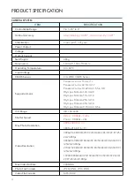
CAMERA SYSTEM

ITEM

SPECIFICATION

Controllable Range

Pitch -90° to 0°

Gimbal Accuracy

Static stability: ±0.005°, motion stability: ±0.01°

Stabilization

3-axis (pitch, roll, yaw)

Power Output
Voltage
Output Current
Net Weight

480g

Dimensions

143mm*110mm*104mm

Operating Temperature

0 to 40°

C

Input Voltage
CMOS Sensor

4/3› WDR CMOS Sensor

Supported Lens

Panasonic Lumix 15mm/1.7 
Panasonic Lumix 42.5mm/1.7 

Panasonic Lumix 14-42mm/3.5-5.6 HD


Olympus M.Zuiko 12mm/2.0 


Olympus M.Zuiko 17mm/1.8


Olympus M.Zuiko 25mm/1.8


Olympus M.Zuiko 45mm/1.8


Olympus M.Zuiko 9-18mm/4.0-5.6

ISO Range

ISO 100-6400

Shutter Speed

Video : 1/8000s – 1/24s


Photo : 

1/8000s – 30s

Max Photo Resolution

4000 x 3000 ( 4 : 3 )

3840 x 2160 ( 16 : 9 )

Video Resolution

4096x2160@100/60/59.94/50/48/47.96/30/29.97/25/

24/23.98fps 

3840x2160@120/100/60/59.94/50/48/47.96/30/29.97

/25/24/23.98fps 

2704x1520@120/100/60/59.94/50/48/47.96/30/29.97

/25/24/23.98fps 

1920X1080@240/120/100/60/59.94/50/48/47.96/30/ 

29.97/25/24/23.98fps

Max Video Bit Rate

200Mbit/s

Photo File Formats

JPEG, DNG, JPG+DNG

Video File Formats

MP4, MOV

Содержание EVOLVE 2

Страница 1: ...USER MANUAL v1 0 2020 06 R Side Bottom 60 View...

Страница 2: ......

Страница 3: ...ned to give you a detailed overview of each element of our product It provides information on how to set up your Evolve 2 and optimise its use for safe flight Please read it carefully before you begin...

Страница 4: ...E 2 1 EVOLVE 2 User Manual 2 Quick Start Guide PRODUCT SUPPORT Store Website Please visit the fly safe page and download information related to the EVOLVE 2 here https store xdynamics com fly safe Sup...

Страница 5: ...n online cloud account before the aircraft can be activated This cloud account downloads all the information and history from the aircraft every time the system is connected to the internet or when a...

Страница 6: ...the aircraft XDynamics LLC is exempt from the user s liabilities for damage s to person s or property or injuries incurred directly or indirectly from the use of this product in the following conditio...

Страница 7: ...ense and requires some basic mechanical abilities Failure to operate this product in a safe and responsible manner could result in injury or damage to the product or other property This product is not...

Страница 8: ..._ _ _ _ _ _ _ _ _ _ _ _ _ _ _ _ _ _ _ _ 30 TURNING ON THE GROUND STATION _ _ _ _ _ _ _ _ _ _ _ _ _ _ _ _ _ _ _ _ _ _ _ _ _ _ _ _ _ _ _ _ _ _ _ _ _ _ _ _ _ _ _ _ _ 31 GROUND STATION LED INDICATORS_ _ _...

Страница 9: ..._ _ _ _ _ _ _ _ _ _ _ _ _ _ _ _ _ _ _ 63 DISARMING THE AIRCRAFT_ _ _ _ _ _ _ _ _ _ _ _ _ _ _ _ _ _ _ _ _ _ _ _ _ _ _ _ _ _ _ _ _ _ _ _ _ _ _ _ _ _ _ _ _ _ _ _ _ _ _ 64 AUTO TAKE OFF _ _ _ _ _ _ _ _ _...

Страница 10: ...PRODUCT PROFILE...

Страница 11: ...t and Ground Station are explained and the individual components are listed The EVOLVE 2 aircraft and Ground Station form a powerful system offering a XXXX low latency FPV video downlink with 4K local...

Страница 12: ...ial images and edit your footages more conveniently Ultra Precise Positioning System Combined with algorithms and a comprehensive suite of positioning tools including a GNSS module that supports GPS Q...

Страница 13: ...11 EVOLVE 2 User Manual V1 0 by XDynamics Limited...

Страница 14: ...6 Motor 7 Forwarad Vision System 8 Lens 9 Propellers 2 CW and 2 CCW 10 Camera CFast Port 11 Gimbal Button 12 Gimbal 13 Camera 14 Battery Display 15 Battery 16 Battery Release Latch Side 17 Magnesium...

Страница 15: ...gnal LED 10 Speaker 11 RTH Button 12 Battery Charging Port 13 Customizable Button C2 14 Customizable Button C4 15 Customizable Button C1 16 Customizable Button C3 17 Triport 18 Battery Level Checking...

Страница 16: ...AIRCRAFT...

Страница 17: ...for full lifetime of the aircraft and improve electrical performance The white appearance is normal The user MUST not attempt to replace the grease with any other products No attempts should be made t...

Страница 18: ...aircraft or battery charger When removing the battery from the aircraft allow the battery to cool to room temperature before charging the battery with the supplied charger See diagram for removing the...

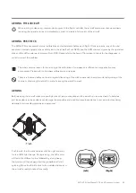
Страница 19: ...o pilot error Therefore it is very important to practice piloting in the proper orientation This includes Positioning the aircraft s nose or front end away from the pilot Be sure to stand at least 6ft...

Страница 20: ...18 BEGINNER MODE User may enable Beginner Mode at the Settings Page After enabling the Beginner Mode the aircraft can only be flown within a spherical radius of 30m from the take off point...

Страница 21: ...r smoother breaking reactions and camera panning while filming 2 Position Mode Center position on 3 position Switch In this mode the aircraft will hold position using the GPS and or optical flow When...

Страница 22: ...led in the aircraft or not If the battery is still turned on when removed from the aircraft ensure the battery connect terminals are left unobstructed to prevent short circuiting Press and release the...

Страница 23: ...TURN OFF THE AIRCRAFT Press and release the battery switch then press again and hold battery switch short press long press until the 4 lights disappear in succession then release The aircraft is powe...

Страница 24: ...the battery or try to connect to any other equipment other than the EVOLVE 2 aircraft and the supplied charger Turning the Battery Off When not Plugged into the aircraft The aircraft is powered on wh...

Страница 25: ...aircraft The LED indicates the current state of the aircraft See diagrams below for indications Initializing Waiting for RC Signal Front Solid Red LED Rear Red Green Yellow alternating fast blinking L...

Страница 26: ...icates the current state of the aircraft See diagrams below for indications Altitude Mode Can be flown in GPS Mode Front Solid Red Rear Solid Yellow Sets home position Sport Mode Front Solid Red Rear...

Страница 27: ...r of the aircraft The LED indicates the current state of the aircraft See diagrams below for indications Landing Mode Front Red Front Rear Blue Solid Make Sure Landing Zone is Clear Malfunction During...

Страница 28: ...confirm the state of the camera such as taking video or taking still photography Camera LED Status GREEN on Normal Idle GREEN toggles Single Shot GREEN toggles rapidly till shots complete Burst GREEN...

Страница 29: ...s crucial to safety and flight planning During flight you can monitor the aircraft s battery level on the top right corner of the top screen using both battery icon and charge percentage located besid...

Страница 30: ...AC Power Cord Cable 2 Adaptor 3 Charger Spliter Block 4 Aircraft Battery Connector 5 Ground Station Battery Connector Follow the steps below to charge the aircraft battery 1 Connect charger to a power...

Страница 31: ...e estimated flight times for battery percentages Battery Warming Signal Consider the following battery levels for decision making 20 30 low battery warning RTH 10 Land Immediately The battery failsafe...

Страница 32: ...GROUND STATION...

Страница 33: ...this double press procedure assures that accidental power ups will not happen While the Ground Station is initializing power on the aircraft battery Refer to Turn On Off aircraft It is important to po...

Страница 34: ...tion LED will be blinking Red until the battery is fully charged and the LED stops blinking constant off During normal operation the LED will be displayed in constant blue When the Ground Station batt...

Страница 35: ...ics Limited FLIGHT MODE MODE 2 Throttle Increase Aircraft rises up Move left thumbstick up Keep right thumbstick centerd Throttle Decrease Aircraft lowers down Move left thumbstick down Keep right thu...

Страница 36: ...DE 2 Yaw Counter Clockwise Aircraft rotates CCW Move left thumbstick left Keep right thumbstick centerd Yaw Clockwise Aircraft rotates CW Move left thumbstick right Keep right thumbstick centerd Left...

Страница 37: ...Limited FLIGHT MODE MODE 2 Forward Movement Aircraft tilts forward Keep left thumbstick centerd Move right thumbstick up Backwards Movement Aircraft tilts backwards Keep left thumbstick centerd Move r...

Страница 38: ...MODE MODE 2 Roll Left Aircraft moves left Keep left thumbstick centerd Move right thumbstick left Roll Right Aircraft moves right Keep left thumbstick centerd Move right thumbstick right Left Left Ri...

Страница 39: ...y mechanical latches and pulling the battery out of the aircraft See diagram for battery installation below Steps for removing the Ground Station Battery 1 First ensure the battery is turned OFF 2 Sli...

Страница 40: ...rted into the Ground Station s main housing Follow the steps below to charge the Ground Station battery 1 Connect charger to a power source 2 Connect the Ground Station Battery 3 Connector to the Grou...

Страница 41: ...APPLICATION...

Страница 42: ...i Signal 7 GPS Signal and number of GPS 8 Remote Controller Signal 9 Image Transmission Signal 10 Drone Battery 11 Remote Controller Battery 12 Time 13 Remain Flight time 14 AE Lock 15 Switch Photo Vi...

Страница 43: ...REEN INTRODUCTION Flight Data is displayed as below 1 Home Button 2 Pilot Name 3 Display Mode 4 Drone Setting 5 Map Option 6 Compass 7 Map 8 Drone Location 9 Home Point 10 Remote Controller Location 1...

Страница 44: ...arnings at the top left corner The bottom screen also shows the alerts on the left side You may also refer to the Alert button at the top right corner for current warnings Alert button at the top righ...

Страница 45: ...he settings menu allows the operator to configure the aircraft to suit their preferences Settings include Aircraft Ground Station Battery Gimbal Map and General Aircraft Settings Ground Station Settin...

Страница 46: ...Smart Pilot System aircraft Pairing Page Settings Ground Station Pairing 2 Turn on the aircraft 3 Keep the aircraft at least 3ft away from the Ground Station 4 Tap Start Pairing on the Ground Station...

Страница 47: ...w the steps below to download the map 1 Connect Ground Station to WiFi internet connection with download capabilities 2 Navigate to the Smart Pilot System Offline Map Page Setting Map Offline Map 3 Ta...

Страница 48: ...ome RTH from last waypoint Auto mode can be cancelled any time by switching the flight mode switch to the left for GPS mode The pilot has full control of the position and yaw angle of the aircraft dur...

Страница 49: ...ound at the camera settings page in the Smart Co Pilot System Select the icon indicated in the diagram below to open the configure settings for the camera The standard settings are similar to those fo...

Страница 50: ...the screen 4 The top screen shows the photos videos in full screen mode while the bottom screen provides the detailed information and control for the photos videos 5 Tap Edit on the top right corner t...

Страница 51: ...Wi Fi Network page on the Smart Pilot APP and connect to the desired Wi Fi network BLUETOOTH To listen to voice alerts form the Smart Piot APP the Ground Station must be connected to connect to Bluet...

Страница 52: ...rmware Update requests are displayed on the Ground Station screen Whenever an update is available the Smart Co Pilot system will request the operator perform the update when the Ground Station is conn...

Страница 53: ...FLIGHT...

Страница 54: ...orecasting weather Executing flight plan and go or no go situations based on the weather information Be sure to make informed decisions based on accurate weather information and remember no flight is...

Страница 55: ...essary Flight Mode Switch P mode VERY IMPORTANT for BEGINNERS CHECK COMPLETE 4 Ground Station Before Aircraft Initialization Checklist Power On Ground Station Pilot App Launch Aircraft initialization...

Страница 56: ...Assenting 16 4ft s 5m s Descending 6 6ft s 2m s Horizontal 47mph 75km h For higher top speeds contact customer support for signing of warranty wavier prior to activation Distance 3281ft 1000m Height...

Страница 57: ...owing page to ensure all propellers are securely in place See diagram for attaching and detaching the propellers Ensure that both CW props with white circle markings match motors with white circle mar...

Страница 58: ...1 Ensure that the CW CCW direction of the propeller is aligned with the direction of the motor Step 2 Place the propeller on top of the motor apply a downward force Hold the motor still and twist the...

Страница 59: ...erhead structures or trees that might interfere with the EVOLVE 2 connecting to GPS satellites Do not place the EVOLVE 2 on metal surfaces or with metal nearby metal interferes with the internal compa...

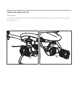
Страница 60: ...58 CAMERA AND GIMBAL SECTION Removing lens To remove the Lens press the button located underneath the gimbal backward then unscrew the lens CCW as shown in the diagram below...

Страница 61: ...move the propellers from the aircraft 2 Make sure the GS and aircraft are powered on and connected 3 Navigate to the accelerometer calibration page on the smart pilot APP Settings General Sensor Accel...

Страница 62: ...60 AIRCRAFT CALIBRATION Accelerometer calibration procedures...

Страница 63: ...ation until the metal interference is gone If relocating the aircraft does not clear the compass error or if the smart pilot APP requires a compass calibration follow the steps below To calibrate the...

Страница 64: ...62 AIRCRAFT CALIBRATION Compass calibration procedures...

Страница 65: ...compass on a different or magnetically noisy environment Please refer to Compass calibration and try again There is a 5 second delay on the arming and disarming of the stick commands to avoid accident...

Страница 66: ...is still in arming mode keep the sticks in the same position until all the LEDs are solid either Green or Blue Push the left throttle stick down and to the left and wait for the LED s light change Du...

Страница 67: ...Short Press and Long Press the Auto Take Off button for 3 seconds 2 The aircraft will arm itself and take off 3 The aircraft will rise to 4 to 5 feet If the aircraft is in GPS mode it will hold posit...

Страница 68: ...o Take Off button for 3 seconds 2 The Ground Station will voice over to indicate the aircraft ready to descent during the descent the operator can reposition the aircraft to clear obstacles or land in...

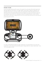
Страница 69: ...en land automatically During the landing descent the operator can move the aircraft s position to clear away from obstacles on the ground or land in a preferred spot At any point during the RTH mode i...

Страница 70: ...altitude than the programed altitude it will remain at that altitude and then return to the Home Point in shortest path straight line 4 Smart Pilot System indicates the aircraft is under Return to Hom...

Страница 71: ...urn home flight the user may stop the Return to Home process by following the steps below 1 Press the cancel button to stop the Return to Home process 2 The aircraft will continue in the mode at which...

Страница 72: ...allows the aircraft to reach a programed altitude before starting to flying back to the home position If the aircraft is below the programed altitude it will ascend to the programmed altitude then pr...

Страница 73: ...APPENDIX...

Страница 74: ...mm 3 5 5 6 HD Olympus M Zuiko 12mm 2 0 Olympus M Zuiko 17mm 1 8 Olympus M Zuiko 25mm 1 8 Olympus M Zuiko 45mm 1 8 Olympus M Zuiko 9 18mm 4 0 5 6 ISO Range ISO 100 6400 Shutter Speed Video 1 8000s 1 24...

Страница 75: ...Time lapse Slow motion HDR10 Photo Mode Single shot Burst Shot Bracketing Interval Timer Shot HDR Exposure mode Auto Manual TV AV Metering Mode Center weighted Evaluative Partial Spot White balance Au...

Страница 76: ...ting Luminance 1000 1200cd m2 Embedded Camera 2592 1944 Front Camera R C Telemetry Operating Frequency Max Transmission Distance 11 km FCC Compliant unobstructed and no interference Live View Working...

Страница 77: ...released Operating Voltage 10 8V Dimensions 9 1in D x 7 1in H x 4 1in W 231 4 x 180 x 103 mm Weight including battery 3 40 lbs 1 55kg GROUND STATION BATTERY ITEM SPECIFICATION Capacity 6700 mAh Li Po...

Страница 78: ...Motors 6600rpm Max Ascent Speed 5m s Max Descent Speed 2 5m s Max Wind speed 7 9m s Max Horizontal Speed 25m s have to test IP rating Operating temperature 10 C 45 C AIRCRAFT BATTERY ITEM SPECIFICATIO...

Страница 79: ...77 EVOLVE 2 User Manual V1 0 by XDynamics Limited...

Страница 80: ...s Otherwise the battery control board may malfunction and cause a serious accident during flight Never disassemble or pierce the battery in any way or the battery may leak catch fire or explode Electr...

Страница 81: ...en it is idle for more than 10 days to prevent it from swelling It takes approximately 3 days to discharge the battery to 65 It is normal that you may feel moderate heat emitting from the battery duri...

Страница 82: ...h denatured alcohol or other flammable solvents Never use a damaged charger Battery Storage Keep batteries out of the reach of children and pets DO NOT leave the battery near heat sources such as a fu...

Страница 83: ......

Страница 84: ...USER MANUAL v1 0 2020 06...

Отзывы: