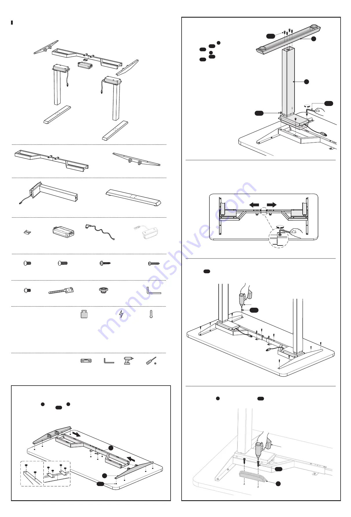
2. Assembling Lifting Columns and Feet
C
D
S-B
S-A
S-H
• Insert one lifting column into one end of
the crossbar with the head of the lifting
column facing inward.
• Fix the
lifting column
with crossbar
using
4 screws
with the
Allen
wrench
.
• Attach the
foot
to the lifting column
using
4 screws
with
Allen
wrench
.
• Repeat the same process to assemble the
other lifting column and foot.
C
S-A
S-H
D
S-B
S-H
What tools are needed to
assemble the desk frame?
What important specifications
should know before installation?
Power Input
(100~240V)
Operation Temperature
(-5°C~+40°C)
Bubble Level
Allen Wrench
(Included)
Drill
Weight Capacity
125kg/275lbs
Phillips Screwdriver
S-A (x8)
Hex Head Screw
S-B (x8)
Hex Head Screw
S-C (x12)
Phillips Head Screw+ 1 Spacer
S-D (x5)
Phillips Head Screw
S-E (x2)
Phillips Head Screw
S-G (x12)
Anti-Vibration Pad
S-H (x1)
Allen Wrench
Checklist and Installation
Please check all of the components shown in the component checklist. If any of the components are missing or damaged,
contact your point of purchase for a replacement.
A (x1)
Crossbar
B (x2)
Side Bracket
C (x2)
Lifting Column
D (x2)
Foot
E (x1)
Fixing Plate
F (x1)
Control Box
G (x1)
Power Cord
S-F (x3)
Cable Clip
3. Adjusting the Frame
• Loosen the hex head screws that fix the adjustable junction,
but don't completely take out the screws.
• Ensure that the frame is placed in the center of the table.
• Then adjust the frame to suit the size of the desktop.
• Retighten all the hex head screws to finish the adjustment.
When adjusting the frame position, please make sure it doesn't exceed the
Max
marked on the inner crossbar.
M
A
X
4. Attaching the Frame to the Desktop
Drill
• Drill
screws
from the backside of the desktop through
12 mounting holes as shown.
S-C
S-C
S-D
Drill
H
H (x1)
Controller
The picture of the controller is for your
reference only. Actual product may vary.
5. Attaching the Controller
• Attach the
Controller
to the desktop with
2 Screws
using a
drill
.
H
S-D
Note:
The picture of the controller is for your reference only. Actual product may vary.
1. Attaching Side Brackets
• Place a shipping blanket on the floor to prevent scratches.
• Carefully place the desktop (not included) upside down on the blanket.
• Place the
crossbar
and
side brackets
on the top.
• Attach the
anti-vibration pads
from below to the positions as shown.
• Attach the side brackets to the end of the crossbar. (This step doesn't require the use of the screws.)
Note:
The drawings of both of the crossbar and side brackets are the
backside
of the components. Please make
sure the crossbar and side brackets keep facing down while installation, which is convenient for the further steps.
S-G
A
B
B
A
S-G
(
Weight Capacity Functionally Rated
)
SPECIAL NOTE:
Should the desk lose power or be unplugged and the loaded weight exceeds 176lbs,
the desk may begin to automatically lower itself. This is normal and a safety feature
designed to reduce the risk of accidents during power outages. Never overload your
desk and maintain clean space beneath it at all times.


