

Technical Specifications
NOTE:
Specifications are subject to change without prior notice.
DC input voltage range
+10.5–15 Vdc
Operating DC voltage range
+9–15 Vdc
Input current range
30 mA (60 mA at LED test)
Operating ambient temperature
0–50 °C
Dimensions (L×W×H)
4
9
/
16
× 1
3
/
4
× 3
9
/
16
in. (114.64 × 44.39 × 89.64 mm)
975-0373-01-02_Rev-A(TC2 Remote Panel Parallel).fm Page 2 Wednesday, December 8, 2010 9:40 AM
Configuring the Charger Mode
NOTE:
By default, the Charger Mode is set to three-stage.
1. Press and hold the
Status
button for five seconds to enter Setup mode. Entering Setup mode will enable you to
select the charger mode.
2. Press
on/standby
button to select the desired charger mode.
The LEDs will indicate which of the two types is being selected: three-stage (default) or two-stage.
3. Press and hold the
Status
button for five seconds to exit Setup mode and save the new setting.
Configuring the Battery Bank Type
NOTE:
By default, the Battery Type is set to Flooded.
1. Press and hold the
Status
button for five seconds to enter Setup mode. Entering Setup mode will enable you to
select the battery type.
2. Press
Set Max Output
button to select the proper battery type.
The LEDs will indicate which of the four types is being selected: Flooded (default), GEL, Lead Calc., or AGM.
NOTE:
If a custom battery type has been programmed by the OEM, then all four LEDs will light up to indicate a
fifth type. To select the OEM battery type, use the Truecharge2 Battery Charger control panel.
3. Press and hold the
Status
button for five seconds to exit Setup mode and save the new setting.
Configuring the Maximum Output Current Percentage of the Charger
NOTE:
By default, the Max. Output % is set to 100.
• Press the
Set Max Output
button to select the appropriate maximum output setting.
The LEDs will indicate which of the five values is being selected: 100, 80, 60, 40, or 20.
NOTE:
The equalization charge current may be affected. See note under Description for Set Max Output
Button.
NOTE:
If operating two Truecharge2 Battery Chargers in parallel, configuration settings made via the remote
panel or primary charger will be applied to both chargers. Settings cannot be changed via the secondary
charger.
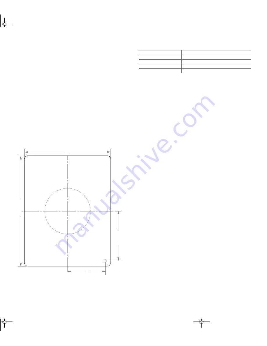
Mounting Template
Figure 2
Truecharge2 Remote Panel Mounting Template (1:1)
1
14.
64
m
m
3m
m
48
m
m
89.
64
m
m
39
.42
m
m
51
.92
m
m
Xantrex
,
Truecharge
, and
Smart choice for power
are trademarks of Schneider Electric Services International sprl, registered in the U.S. and other countries. Other trademarks, registered trademarks, and product names are the property of their
respective owners and are used herein for identification purposes only. Truecharge2 Remote Panel Installation Instructions, Xantrex Technology USA Inc. (“Xantrex”): (
A
)
MAKES
NO
WARRANTY
AS
TO
THE
ACCURACY
,
SUFFICIENCY
OR
SUITABILITY
OF
ANY
TECHNICAL
OR
OTHER
INFORMATION
PROVIDED
IN
ITS
MANUALS
OR
OTHER
DOCUMENTATION
, (
B
)
ASSUMES
NO
RESPONSIBILITY
OR
LIABILITY
FOR
LOSSES
,
DAMAGES
,
COSTS
OR
EXPENSES
,
WHETHER
SPECIAL
,
DIRECT
,
INDIRECT
,
CONSEQUENTIAL
OR
INCIDENTAL
,
WHICH
MIGHT
ARISE
OUT
OF
THE
USE
OF
SUCH
INFORMATION
. T
HE
USE
OF
ANY
SUCH
INFORMATION
WILL
BE
ENTIRELY
AT
THE
USER
’
S
RISK
;
AND
(
C
)
REMINDS
YOU
THAT
IF
THIS
MANUAL
IS
IN
ANY
LANGUAGE
OTHER
THAN
E
NGLISH
,
ALTHOUGH
STEPS
HAVE
BEEN
TAKEN
TO
MAINTAIN
THE
ACCURACY
OF
THE
TRANSLATION
,
THE
ACCURACY
CANNOT
BE
GUARANTEED
.