


3
Modules & Connecting Blocks
789-44
Fig. 3
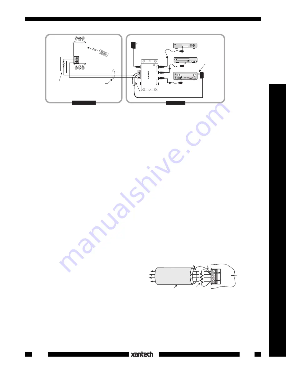
Using the STATUS terminal in a typical system (see text, pg 4).
6-15-00
Using The "STATUS" Terminal on the 789-44
Fig. 3 illustrates a single zone system where the Status LED on a Xantech 780-80 IR Receiver, in the remote
room, shows the ON/OFF status of an A/V receiver.
• The STATUS and GND terminals on the 789-44 provide convenient tie points for the voltage that drives
STATUS indicators on certain Xantech products (such as the 780-80 IR Receiver).
To connect such a system, proceed as follows:
1. Be sure all power plugs for the A/V system are un-plugged before proceeding with the following
connections.
2. Plug a 12V adapter, such as the Xantech 786-00 Power Supply, into the switched
AC Outlet on the
back of the A/V receiver (or integrated amplifier, preamp, etc.).
3. The 12V leads of the adapter (cut attached plug off) are then connected between the STATUS and
GND terminals on the 789-44 ("+" to STATUS, "–" to GND).
4. You would then connect the 4-conductor inter-room cable between the 789-44 and the 780-80 as
shown in Fig. 3.
5. If you wish to adjust the brightness of the Status LED, place a resistor in series with the STATUS lead
as shown in Fig. 3. Use a value that achieves the desired brightness level (usually 1k Ohm to 10k Ohm,
1/8 watt).
CAUTION NOTE
When using long lengths (>50 ft.) of inter-room
shielded cable, it may be necessary to connect a
470 Ohm 1/8 Watt resistor between IR IN and
GND at the connector terminals of the 789-44.
Refer to Fig.4.
The resistor discharges the cable capacitance
more quickly, allowing IR codes of high bit rates
to pass without data loss.
MOUNTING
The 789-44 can be conveniently mounted to a wall or shelf by using the two sheet-metal screws supplied.
The unit may be mounted in any orientation to accommodate the installation.
+ 1 2 V D C
G N D
S TAT U S
I R I N
470 Ohm
resistor
Shielded Cable
to remote room
789-44 Input
Terminals
Ground Shield as shown
Fig. 4
470 Ohm Capacitance Discharge Resistor
+12VDC
STATUS
GND
IR OUT
780-80
IR RECEIVER
XANTECH CORP
.
SYLMAR, CA
91342
283M
Blink-IR™
Mouse Emitter
To 120 V AC
(unswitched)
781RG
Power Supply
789-44
Connecting Block
283M
Blink IR™
282M
Emitter
Hand Held
Remote
VCR
GND
IR OUT
+12V
780-80
J-Box
IR Receiver
(rear view)
4-Conductor
Inter-room Cable
(unshielded OK)
STATUS
White Striped Side ("+")
786-00
Power Supply
(12V at 10 mA)
Plug into
Switched AC Outlet
on A/V Receiver
(see text)
Add resistor in series
with STATUS line to
adjust brightness, if desired.
(See text, next page).
REMOTE ROOM
MAIN ROOM
–
+
12VDC
+12 VDC
GND
STATUS
IR IN
EMITTERS
IR
RCVR
789-44
CONNECTING BLOCK
®
A/V Receiver
Satellite Receiver