background image

11

AK11A-08/00

10

AK11A -08/00

I

F


YOU


ARE


NOT


GETTING


ANY


SIGNAL


AT


ALL

Check that the CHANNEL slide switch (labeled A, B, C, D) on both
units (on bottom) is set to the same letter.

I

F


THE


SIGNAL


IS


POOR

OR


THERE


IS


INTERFERENCE

Try changing the channel on both units. Do this by adjusting the
CHANNEL slide switch on the bottom of each unit to any position
from A to C. Make sure both units are set to the same channel.

 F

INE

 T

UNING


YOUR

 S

YSTEM


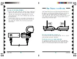
The Wireless Audio Sender usually works best with the flat faces of
the antennas on the Sender and Receiver unit facing each other (i.e.
in “Line of sight” - see diagram below). Sometimes, however,
reflections and other effects in the home may affect the signal so that
some adjustment of either the Sender or Receiver antenna may be
necessary to get the best the signal.

H

OOKING


UP


THE

 A

UDIO

 R

ECEIVER

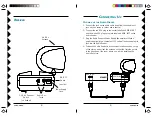
1. Connect a set of Audio cable to the audio OUT jacks on the Audio

Receiver. Connect the other end to your stereo system's amplifier.

2. Plug the Audio Receiver's Power Supply (the larger of the two

power supplies) into a 120 volt wall outlet and plug its jack into
the Audio Receiver.

3. Position the Audio Receiver in a convenient location such as on

top of your stereo system and orient the antenna so that the flat
side points in the direction of the room where you set up the
Audio Sender.

A MP

AUDIO OUT

AUDIO IN

Содержание AK11A

Страница 1: ...OWNER S MANUAL Audio Sender AUDIO EXTENDER SYSTEM MODEL AK11A INCLUDES AT11A SENDER AR11A RECEIVER WIRE LES S AUDIO SENDER WIRELESS AUDIO RECEIVE R...

Страница 2: ...nded by the manufacturer 9 A product and cart combination should be moved with care Quick stops excessive force and uneven surfaces may cause the product and cart combination to overturn 10 Ventilatio...

Страница 3: ...onal suggestions NOTE Modifications to this product will void the user s authority to operate this equipment 11 Power Sources This product should be operated only from the type of power source indicat...

Страница 4: ...2 4 GHz Channel Switch on bottom CHANNEL A BC D CHANNEL ABC D CONTENTS CONTROLS AND CONNECTIONS 7 SENDER 7 RECEIVER 8 CONNECTING UP 9 HOOKING UP THE SENDER 9 HOOKING UP THE RECEIVER 10 FINE TUNING YOU...

Страница 5: ...s Power Supply the smaller of the two power supplies into a convenient 120 volt wall outlet and plug its jack into the Audio Sender 4 Position the Audio Sender in a convenient location such as on top...

Страница 6: ...in Line of sight see diagram below Sometimes however reflections and other effects in the home may affect the signal so that some adjustment of either the Sender or Receiver antenna may be necessary...

Страница 7: ...PRODUCTS WHICH HAVE BEEN SUBJECT TO MISUSE NEGLECT ACCIDENT INCORRECT WIRING OR TO USE IN VIOLATION OF OPERATING INSTRUCTIONS FURNISHED BY US NOR EXTEND TO ANY UNITS ALTERED OR REPAIRED FOR WARRANTY D...

Отзывы: