background image

ASSEMBLY AND OPERATING INSTRUCTIONS 


1. 

    CAUTION!  

Always make sure the ignition switch is in its “

OFF

” position and the 

ignition Key is removed prior to setting up the XT-300, adding any accessories, or making 

adjustments to the unit. 


2.  The Scooter comes fully assembled, but will require some setup as follows: The Steering 

Bar Assembly must be positioned in place, the Wheels must be inflated and the Batteries 

must be charged. 


Raise, lock, And Adjust The Steering Bar Assembly:


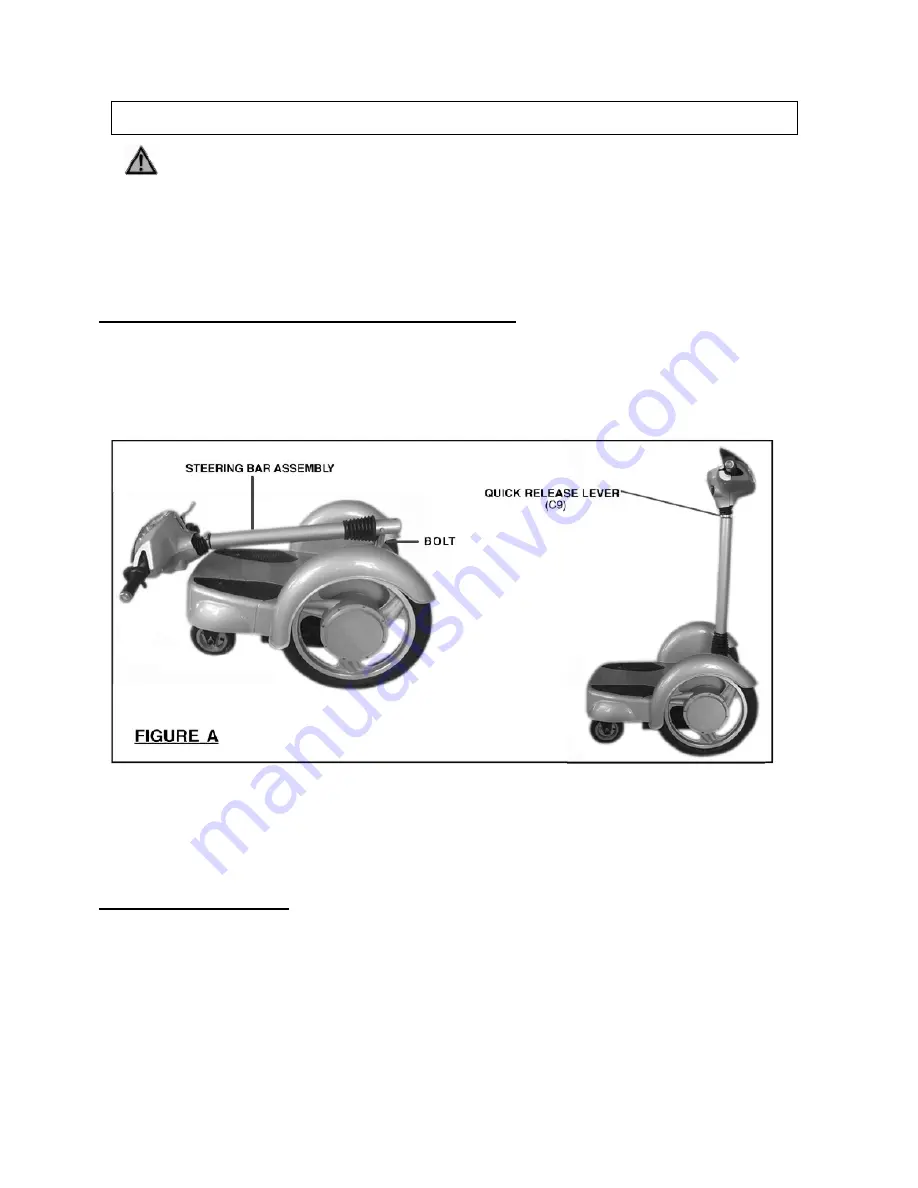
1.  Remove the Bolt illustrated below.

 (See Figure A.)


2.  Lift the Steering Bar Assembly all the way up to its vertical position. Then, insert the Bolt 

you removed previously back into the same hole and firmly tighten it.

 (See Figure A.)


3.  Push the Quick Release Lever (C9) down to lock the Handle Bar in place. 

(See Figure A.)


4.  To adjust the height of the Handle Bar, unlatch the Quick Release Lever (C9). Adjust the 

Handle Bar to a comfortable height. Then, lock the Quick Release Lever (C9) in place. 

(See Figure A.)


Install Power Pack Plug 


1.  Lay the XT-300 down so that you can locate the power pack plug under the scooter on the 

left side.   


2.  Insert the plug into the power pack as show below.     


3.  Return the scooter to its upright position. 


Page 6

Содержание XT300

Страница 1: ...l XT300 Due to continuing improvements actual product may differ slightly from the product described herein Visit our Web site at http www x tremescooters com TO PREVENT SERIOUS INJURY READ AND UNDERSTAND ALL WARNINGS AND INSTRUCTIONS BEFORE USE Page 1 ...

Страница 2: ...W 28 1 2 L Unit Weight 114 Pounds Standard Features Forward Reverse Modes Foldable Handle Key lgnition Adjustable Height Handlebars Headlight Electric Horn Front Facing Left Right Turn Signals Battery Indicator Gauge Speed Indicator Gauge LED Power headlight Display Battery Charger Warning This Scooter is not designed to be driven on roads Streets highways or other public roadways Never operate th...

Страница 3: ...this product while tired or under the influence of drugs alcohol or medication A moment of inattention while operating the XT 300 may result in serious personal injury 7 Never carry a passenger on the XT 300 This Scooter is designed for single rider only 8 This Scooter is designed to be operated only on dry flat paved surfaces Never operate the XT 300 off road Never operate the XT 300 on roads str...

Страница 4: ...tric shock 20 When operating the XT 300 always maintain a firm grip on the Handle Bars with both hands to maintain control 21 Do not over stress the XT 300 This product will be easier and safer to ride at the speed and capacity for which it was designed 22 The charge time for the Battery is 5 hours Do not charge the Battery for over 5 hours as damage to the Battery and or XT 300 may result 23 Alwa...

Страница 5: ...by poorly maintained products 31 Scooter service must be performed only by qualified repair personnel Service or maintenance performed by unqualified personnel could result in a risk of injury 32 When servicing the Scooter use only identical replacement parts Follow instructions in the Inspection Maintenance And Cleaning section of this manual Use of unauthorized parts or failure to follow mainten...

Страница 6: ...ated below See Figure A 2 Lift the Steering Bar Assembly all the way up to its vertical position Then insert the Bolt you removed previously back into the same hole and firmly tighten it See Figure A 3 Push the Quick Release Lever C9 down to lock the Handle Bar in place See Figure A 4 To adjust the height of the Handle Bar unlatch the Quick Release Lever C9 Adjust the Handle Bar to a comfortable h...

Страница 7: ...Inflate The Wheels Make sure to inflate the front and back Wheels to 36 PSI Do not exceed 36 PSI Use compressed air only Product Features Page 7 ...

Страница 8: ...d Plug into the nearest 120 Volt grounded electrical outlet See Figure C 4 Charge the Scooter for 5 hours A red LED light will illuminate on the Gauge Panel of the Scooter while it is being charged Once the Scooter is fully charged the red LED Light will automatically turn to green Note when the Voltage Gauge on the Gauge Panel indicates 42V 43V that also means a full charge If the Voltage Gauge i...

Страница 9: ...u release it See Figure B 3 Check the Wheels 12 24 for wear and proper air pressure 36 PSI See Assy Diagram on page 12 4 Check to make sure the Headlight Turn Signal Lights and Horn are working properly See Figure B Operating points 1 WARNING This Scooter is not designed to be driven on roads streets high ways or other public roadways Never operate the Scooter off road or off paved surfaces 2 Turn...

Страница 10: ...urs have the problem corrected before further use Do not use damaged equipment 3 If stored for an extended period of time Charge the Battery at least once every 90 days To prolong the life of the Batter discharge the Battery every 90 days Only a qualified service technician should replace the Battery 4 To clean use a clean damp cloth and a mild detergent Do not use solvents Do not spray water on t...

Страница 11: ...sible Solution The power light on the gauge panel does not light up when the Scooter is turned on 1 Battery is discharged 2 Blown instrument Panel Fuse 3 Loose electrical connect on inside the Scooter 1 Recharge Battery for 5 hours See page 8 2 Replace Fuse See page 10 3 Have a qualified service technician examine the connections The power light on the gauge panel lights up but Scooter still does ...

Страница 12: ...m Flange 1 16 Hex Nut 2 4 Seal 1 17 Hex Key Screw 4 5 Retaining Ring 1 18 Hex Lock Nut 1 6 Circuit Board 1 19 Hex Key Screw 5 7 Battery Case 1 20 Hex Bolt 1 8 Panel 1 21 Hex Bolt 1 9 Scooter Frame 1 22 Bearing 2 10 Rear Wheel Bracket See List and Diagram A 1 23 Left Brake 1 11 Coupling Bar 1 24 Front Wheel 2 12 Wheel Assembly See List and Diagram B 2 13 Steering Bar Assembly See List and Diagram C...

Страница 13: ...3 Retaining Ring 2 A4 Retaining Ring 4 A5 Flat Washer 10 A6 Pin 2 A7 Cam Bracket 1 A8 Transverse Coupling Bar 2 A9 Cam Flange 2 A10 Pin 2 A11 Frame 1 A12 Ball Bearing 5 A13 Hex Screw 2 A14 Hex Key Screw 2 NOTE Some parts are listed and shown for illustration purposes only and are not available individually as replacement parts Page 13 ...

Страница 14: ...tor 1 B3 Inner Hub 1 B4 Outer Hub 1 B5 Hex Locking Screw 1 B6 Cap Screw 1 B7 Cross Countersunk Screw 6 B8 Cap Screw 3 B9 Bushing 1 B10 Flat Hook Washer 2 B11 Wheel 1 NOTE Some parts are listed and shown for illustration purposes only and are not available individually as replacement parts Page 14 ...

Страница 15: ...Y DIAGRAM C STEERING BAR ASSY Part Description Q ty C1 Column 1 C2 Seal 1 C3 Dust Cover 1 C4 Handlebar 1 C5 Front Panel Cover 1 C6 Rear Panel Cover 1 C7 Grip 2 C8 Brake Handle 2 C9 Quick Release Lever Assembly 1 Page 15 ...

Страница 16: ...ENJOY YOUR RIDING For General Information or Parts Visit www x tremescooters com For Technical Support or Assistance Visit www x tremescooters com support Page 16 ...

Отзывы: