


11
®
LEADERS IN POLE & AERIAL FITNESS
Copyright© Vertical Leisure Ltd. 2020 Version 3.0
All rights reserved.
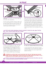
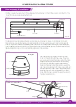
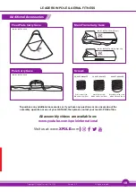
Bearing Unit - Spinning Mode
Cone
Bearing Body
Pole Retaining
Screws (M8)
Free Spin
'A' Pole
Static & Spinning Screws
(M10)
Bearing Unit
Pole assembly & installation
The Bearing Unit must be treated with great care and steps should be taken to ensure it is not dropped or knocked.
Remove the band securing the bearing unit, while holding the unit in place and making sure it does not slide down the
pole. It is important to understand the Bearing Unit’s operation as this will help when assembling and disassembling the
pole. The Bearing Unit has two sections; an upper angled section (Cone) with 3x M8 hex screws and a lower flat section
(Bearing Body) which has a slot for positioning the bearing unit in the main frame.
Fig. (10.1)
The Pole is made of four parts, the 'A' Pole, a Bearing Unit that attaches to it, the 'B' Pole and an X-Joint (Fig.10.1). The
'A' and 'B' poles are connected using the X-Joint.
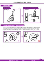
Carry Case
A Pole
Bearing Unit
X-Joint 250mm (9.8”)
B Pole
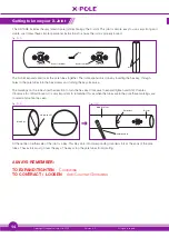
EXPAND
CONTRACT
EXPAND
CONTRACT
Velcro Straps
Protective Pad
Fig. (10.2)
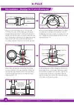
The cone section supports the pole and is secured
to the 'A' Pole with the 3x M8 hex screws. These hex
screws are used to adjust the pole’s position in the Main
Stage Frame assembly. The lower flat section bearing
body is the part that inserts into the stage’s Bearing
Carrier on the Upper Centre Plate and also supports the
pole. This section includes 2x M10 hex screws which set
the 'Static/Spinning' modes of the X-Stage/X-Stage Lite.
When these 2x hex screws are tightened it is in 'Static'
mode. When the hex screws are loosened, the pole is in
‘Spinning’ mode (Fig.10.3).
Fig. (10.3)
Bearing Body
Cone
Bearing Unit
Key Slot
'A' Pole