background image


Insulation Blowing Machine M99


X-Floc Dämmtechnik-Maschinen GmbH 

Page 39 of 51


Rosine-Starz-Straße 12 · 71272 Renningen · Germany 
Phone +49-7159-80470-30 · Fax -40 | [email protected] · www.x-floc.com 


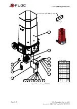
Art.-Nr.: 2271

Pos.-Nr. Menge Art.-Nr.

1

1

2270

2

1

2272

3

1

2273

4

1

2274

5

6

2275

6

2

5666

7

2

099

8

1

6037

9

2

127

10

18

120

11

1

420

12

1

1387

13

6

1504

14

30

107

15

1

124

17

1

101


Figure 35: Blow-up drawing airlock 


1

4

5

5

2

3

6

1

7

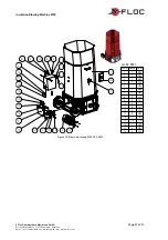
Art.-Nr.: 5803

Pos.-Nr. Menge Art.-Nr.

1

2

3848

2

6

3035

3

6

3964

4

2

1738

5

6

4598

6

6

2755

7

1

5834


Figure 36: Blow-up drawing air supply unit


2

3

4

1

Art.-Nr.: 3449 

Pos.-

Nr. Menge Art.-Nr.

1

1

3313

2

1

1383

3

1

3450

4

1

3451


Figure 37: Blow-up drawing 

suction hood [12]


Содержание Minifant M99

Страница 1: ...ng Machine Minifant M99 F Series Original Operating Instructions Version 2 M99 M99 DS M99 DS Pro X Floc D mmtechnik Maschinen GmbH Rosine Starz Stra e 12 71272 Renningen Germany Phone 49 7159 80470 30...

Страница 2: ...3 4 2 Technical Details 13 4 Preparation 14 4 1 Transport Assembling Connecting 14 4 1 1 Unpacking setup 14 4 1 2 Power Connection 15 4 1 3 Suction Hood 15 4 1 4 Outlet Connection 16 4 1 5 Control Con...

Страница 3: ...1 6 1 11 Airlock Feed Gate 31 6 1 12 Operating Hours Meter 31 6 1 13 Gear Boxes 31 6 1 14 Cleaning 31 6 2 Faults Troubleshooting 32 6 3 Disposal 33 6 3 1 Final Decommissioning 33 6 3 2 Disposal Accord...

Страница 4: ...s surrounding accident prevention and the recognized technical rules governing safe and proper work applicable in the country and at the site of use are to be fully acknowledged Our General Terms Cond...

Страница 5: ...uctions Caution hazard Details instructions and prohibitions regarding damage prevention and personal injury Ignoring this symbol may result in harmful consequences such as fatal injuries WARNING High...

Страница 6: ...be liable for any resulting damage to persons and or objects The insulation blowing machine is not explosion protected and must not be used in potentially explosive areas The use of non approved spar...

Страница 7: ...l commissioning and or operation Prior to maintenance and cleaning work move the net adaptor The workplace related emission sound pressure level measured according to DIN EN ISO 11201 is 70 0 dB A Dep...

Страница 8: ...M99 Pos Control Element Purpose 1 Hopper extension Filling up safety flap 2 Handle Holding device for removing the hopper 3 3 Hopper Filling in 4 Airlock feed gate scale Material dosing airlock feed g...

Страница 9: ...g machine M99 Pos Control Element Purpose 10 Bottom of the machine Suction hood 12 fixing Outlet 7 electric switchboard 6 wheels 13 panelling 11 Intake socket NW75 3 Air supply 12 Suction hood Air fil...

Страница 10: ...for operational readiness 18 Rotary airlock fault light and conditioning unit fault light P4 Display for faults with the rotary airlock 8 and the conditioning unit 9 19 Main switch Q1 Switching the in...

Страница 11: ...M99 M99 DS Figure 5 Side view of the electric switchboard s 6 control elements M99 DS Pro Pos Control Element Purpose 27 Main connection X10 Electrical power point 28 Machine control socket X3 M99 M9...

Страница 12: ...54 FFB2000 Pro connection cable 50m 5280 Suction hose conveyor pipe NW75 3 0 2m 4485 Tool box 2419 For special orders the delivery content is detailed in the delivery papers The delivery has to be che...

Страница 13: ...r 200L Filling height 1400mm Intake socket 11 NW75 3 Outlet 7 NW63 2 Machine control KFB3 and FFB400 FFB2000 Pro Automatic blowing Conveying height without with an amplifier max 20m 40m Air supply uni...

Страница 14: ...e by gripping the hopper s 3 handles 2 is not advised When transporting the machine over palettes or anything similar protect the machine from tipping over or external hindrances In the event of trans...

Страница 15: ...taken to ensure that these are fully laid out There is a risk of overheating and fire Take local conditions into account and prevent the supply cable from being damaged when laying them out The operat...

Страница 16: ...rol connection The cable remote control KFB3 KFB30 and radio remote control FFB400 s connections are made at the electric switchboard s 6 machine control socket X3 28 Open up the machine control socke...

Страница 17: ...nd held control KFB3 Pos Control Element Purpose 32 Toggle switch Choosing the air flow air and material flow OFF 33 Material Activating the air and material flow switching the material flow on 34 OFF...

Страница 18: ...that no one will be disturbed due to the machine s automatic start up 5 1 2 Machine Operation To operate the machine the control must always be connected with the electric switchboard s 6 machine con...

Страница 19: ...FF Material and air flow activation switchover to parameterisation mode key lock activation 40 Antenna Bidirectional radio transmission between hand held control and receiver 41 Connection cable Recei...

Страница 20: ...d it will be deactivated by pressing the Air 44 button 1 Air and material flow activation Air flow turns on Material flow turns on after start delay If air flow is enabled material flow is switched on...

Страница 21: ...delay time can be extended up to a maximum of 9 seconds Shortening the start delay time The material flow s start delay time can be shortened by pressing the AUX 43 button every second The start delay...

Страница 22: ...sful configuration of the hand held control and the receiver will be signalled via short darkening of the LED The program function will remain active for approx 30 seconds and automatically switch its...

Страница 23: ...ity M99 The material 1 put through the insulation blowing machine will be broken up in the rotating conditioning unit 9 2 and transported to the airlock The airlock feed gate 3 controls the insulation...

Страница 24: ...irlock feed gate by positioning the hand lever The current airlock feed gate position can be seen on the airlock feed gate scale 4 5 5 Airlock Rotational Speed DS optional For a finer material flow vo...

Страница 25: ...itial operation the machine must be warmed up for approximately 10 minutes in order to prevent any stoppages with the rotary airlock 8 and loosening unit During the warm up the airlock seals and gearb...

Страница 26: ...4 When operating the insulation blowing machine M99 we recommend the first insulation bales be put into the machine in small pieces and loosened using the conditioning unit maintenance button S1 S2 2...

Страница 27: ...cing There is an increased threat of injury when improper maintenance work is carried out Improper maintenance work can lead to serious injury to both persons and equipment Before starting any mainten...

Страница 28: ...ary get rid of any foreign objects Every 80 operating hours or 1 month for irregular commissioning 1 year Angular gearbox Check the bevel gears for wear and tear slackness and grease If necessary grea...

Страница 29: ...y If there is any abrasion on the sealing rings then there is a higher amount of leaked air during operation Damaged and worn sealing rings must be replaced For further information please contact cust...

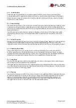
Страница 30: ...ip nut 6 1 7 Conditioning Unit Figure 29 Conditioning unit 9 top view The conditioning unit 9 is located in the machine s bottom 10 A strongly deformed conditioning unit cannot shredder the insulation...

Страница 31: ...eed gate becoming stiff For this reason the collected insulation material between the airlock feed gate and attachment base must be regularly removed 6 1 12 Operating Hours Meter The operating hours m...

Страница 32: ...e current is too high Check the surrounding electrical power s connected load and if necessary disconnect the consumer load from the power The measured value whilst pressure testing see chapter 6 1 5...

Страница 33: ...can and may not fix due to his level of knowledge a qualified specialist must be contacted During final decommissioning disconnect the insulation blowing machine from the power connection and dispose...

Страница 34: ...n extension of the hand held control and the receiver 5280 FFB2000 Pro extension cable L 50m on reel Enables a control and an extension of the hand held control and the receiver 5167 Intake socket 90...

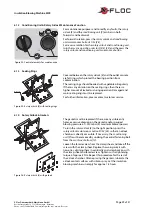
Страница 35: ...Art Nr 3072 11 19 52 20 20 54 53 35 36 Art Nr 5615 DETAIL E DETAIL F DETAIL G Pos Nr Menge Art Nr 1 1 1980 2 1 2271 3 ca 200mm 4495 4 2 3125 5 1 1706 6 2 1499 7 ca 660mm 6034 8 ca 350mm 6034 9 4 5914...

Страница 36: ...gen Germany Phone 49 7159 80470 30 Fax 40 info x floc com www x floc com E 1 2 6 7 5 5 4 3 10 9 4 8 5 5 7 6 11 DETAIL E Passfeder DIN 6885 A 6x6x28 Art Nr 3432 Pos Nr Menge Art Nr 1 1 5615 2 1 5700 3...

Страница 37: ...0 Fax 40 info x floc com www x floc com 1 2 3 4 5 8 9 10 10 9 8 10 11 12 13 14 15 16 17 15 15 18 17 7 6 15 11 13 Art Nr 3837 Pos Nr Menge Art Nr 1 1 5615 2 1 6138 3 1 6138 4 1 305 5 1 4704 6 1 4568 7...

Страница 38: ...11 10 Pos Nr Menge Art Nr 1 1 5615 2 1 5602 3 1 5602 4 1 4704 5 1 305 6 1 4703 7 2 115 8 2 124 9 12 2241 10 14 114 11 6 106 12 2 1181 13 3 101 Figure 33 Blow up drawing M99 DS Pro 3 6kW 12 9 16 8 7 14...

Страница 39: ...3 1 2273 4 1 2274 5 6 2275 6 2 5666 7 2 099 8 1 6037 9 2 127 10 18 120 11 1 420 12 1 1387 13 6 1504 14 30 107 15 1 124 17 1 101 Figure 35 Blow up drawing airlock 1 4 5 5 2 3 6 1 7 Art Nr 5803 Pos Nr...

Страница 40: ...1 5 SW PE U V U U Q1 Hauptschalter P2 Netz spannungs anzeige Optional li re V 1 L1 2T1 Q3 5 6 3L2 4T2 P1 Betriebs stunden z hler h L2 T2 L1 T1 Q2 Gebl se wahlschalter 2 1 1 X1 13 14 15 PE Maschinen an...

Страница 41: ...chnikmaschinen GmbH 2 5 2 230V 3 6kW V3 0 0 T1 24VDC 1A Steuer transformator 1 2 F2 T1 6A PE 9 ob X1 1x0 75 H05V K 0 75 DBL x1 x2 P4 St rung X3 Maschinen steuerungs dose 2 3 4 1 X2 Zusatz ger te dose...

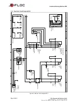
Страница 42: ...42 of 51 X Floc D mmtechnik Maschinen GmbH Rosine Starz Stra e 12 71272 Renningen Germany Phone 49 7159 80470 30 Fax 40 info x floc com www x floc com 7 2 3 Electrical Circuit Diagram M99 DS Figure 4...

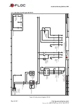
Страница 43: ...ing Machine M99 X Floc D mmtechnik Maschinen GmbH Page 43 of 51 Rosine Starz Stra e 12 71272 Renningen Germany Phone 49 7159 80470 30 Fax 40 info x floc com www x floc com Figure 41 Electrical circuit...

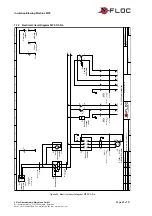
Страница 44: ...ing Machine M99 Page 44 of 51 X Floc D mmtechnik Maschinen GmbH Rosine Starz Stra e 12 71272 Renningen Germany Phone 49 7159 80470 30 Fax 40 info x floc com www x floc com Figure 42 Electrical circuit...

Страница 45: ...x1 5mm H07V K 1 5 SW U V U U Q1 Hauptschalter P2 Netz spannungs anzeige Optional li re V T3 5 5 5 2 Frequenz umrichter L1 R L2 S PE U V W V1 U1 W1 PE M1 0 75kW 3 31A Schleuse R hrwerk 3 M 4x1 5mm 1 m...

Страница 46: ...3 4 15 10 2014 2 2 Name 5 MKl Zu K02 Zusatzschaltanlage T1 24VDC 1A Steuer transformator 1 2 F1 T1 6A PE 9 ob X1 1x0 75 H05V K 0 75 DBL R1B R1C R1A T3 4 2 x1 x2 P4 St rung X3 Maschinen steuerungs dos...

Страница 47: ...7 1 ob ob ob ob ob un 3x1 5mm 1 m YSLY JZ K01 HS 4 4 K01 HS W4ZS PE 2 5x1 5mm 1 m YSLY JZ K01 HS 4 6 K01 HS W5ZS 2 4 1 3 1 PE 3 X1 4 5 6 7 8 14 L1 N T2 7 5 Drehzahlsteller T1 T2 11 6 1 2 PE M2 1 45kW...

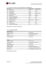
Страница 48: ...r 3 6A 3 5A nSP Rated engine speed 1380 1390R min 1400R min Ctt Engine control type PErF Hrs COS Cosine Phi 0 76 0 77 SLP Slip compensation 7 100 rrS Counter clockwise rotation L2H NO Unlisted paramet...

Страница 49: ...ery Minimum gaps to avoid crushing of parts of the human body DIN EN ISO 11201 Acoustics Noise emitted by machinery and equipment Measurement of emission sound pressure levels at a work station and at...

Страница 50: ...ram M99 40 Electrical circuit diagram M99 DS 42 Electrical circuit diagram M99 DS Pro 45 Emergency 6 Emission sound pressure level 7 Empty weight 13 Engine power 13 Environmental protection 33 Fan pow...

Страница 51: ...rlock fault light 10 Rotary airlock maintenance button 10 Rotary airlock maintenance function 29 Sack support 9 Safety devices 7 Safety notes 6 Sealing rings 29 Serial plate 12 Setup 14 Shredding 13 S...

Отзывы: