Page 2
Page 3
WARNING: Never look at operating light source! The light could severely damage the cornea and retina of the eye if the light is observed directly. Eye
shielding must be used at all times as well as clothing to protect exposed skin
Printed in Canada
Refer to user guide for more details.
035-00603R Rev. 2
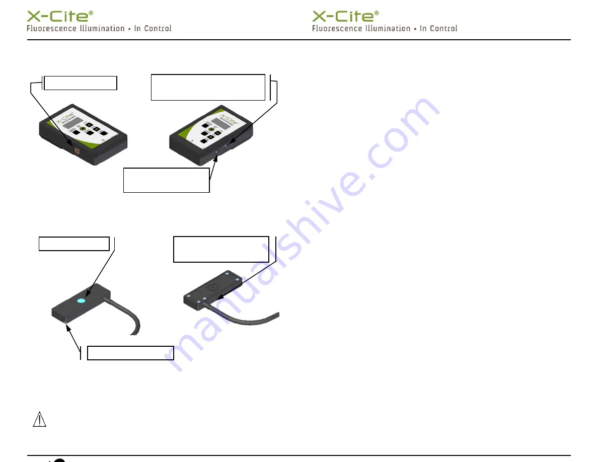
Figure 1: XR2100 Keypad (refer to user guide for complete details)
Figure 2: XR2100 Optical Power Meter Connections
Figure 3: XP750 Top and Bottom Views
Installation and Basic Operation
(refer to user guide for complete details)
XR2100 Optical Power Meter with Light Guide Input
1.
Install the light guide adaptor corresponding to the size of your light guide
into the Optical Input Port of the XR2100. Refer to Figure 1 for location.
2.
Remove light guide from microscope adapter and insert the light guide end
into the light guide adaptor and fasten in place using the supplied thumb
screw.
3.
Set and turn on fluorescence light source to the desired intensity level.
Turn the XR2100 ON.
4.
Use Relative/Absolute button to adjust display mode of measurement.
XP750 with Upright Microscopes
1.
Plug the XP750 multi-pin connector into the XR2100. Refer to Figure 2 for
connecting cable locations.
2.
For upright microscopes, place the XP750 onto the stage with the detection
window (refer to Figure 3) facing up, and approximately centered beneath
the microscope objective lens.
3.
Secure the XP750 in place using the microscope’s stage clip.
4.
Turn on fluorescence light source and ensure that the filter cube in the
beam path is directing visible light to the microscope stage. Ensure the
light is centered within the window.
5.
Press the XR2100 ‘POWER’ button, allow approximately 6 seconds for
initialization. If the display reads ‘LG’, press ‘EXTERNAL’ to change input
channel to the XP750. ‘EXT’ will be displayed at left side of LCD, and the
reading may take several seconds to stabilize.
6.
Press the ‘
(nm)’ button to see the current wavelength setting.
7.
Select the appropriate wavelength by pressing
▲
button repeatedly to
cycle through wavelengths in 1nm increments, or
▼
button to decrement
the wavelength in 1nm increments.
XP750 with Inverted Microscopes
1.
Plug the XP750 multi-pin connector into the XR2100. Refer to Figure 2 for
connecting cable locations.
2.
For inverted microscopes, place the XP750 onto the stage with the
detection window facing down and approximately centered above the
microscope objective lens. The + icon (etched inside a circle) should be
facing up (refer to Figure 3) which marks the center of the detection
window.
3.
Secure the XP750 in place using the microscope’s stage clip.
4.
Turn on transmission light source and using the microscope stage x-y
controls, center the light on the + icon.
5.
Set and turn on fluorescence light source to the desired intensity level.
6.
Press the XR2100 ‘POWER’ button, allow approximately 6 seconds for
initialization. If the display reads ‘LG’, press ‘EXTERNAL’ to change input
channel to the XP750. ‘EXT’ will be displayed at left side of LCD, and the
reading may take several seconds to stabilize.
7.
Press the ‘
(nm)’ button to see the current wavelength setting.
COMPUTER USB PORT
DIN MULTI
-
PIN CONNECTION PORT
FOR EXTERNAL SENSORS
,
XP750
X
-
CITE
exacte
STEREO
CONNECTOR PORT
DETECTION WINDOW
CUT
-
OUT FOR STAGE CLIP
CENTER POINT OF DETECTION
WINDOW
(+
ICON
)


