


6
Technical Support: [email protected] US: +1 866 677 0053 EU: +44 (0) 1793 230 343
EX-1UTP-IR-100-EDID RECEIVER AND CONNECTION & OPERA
TION
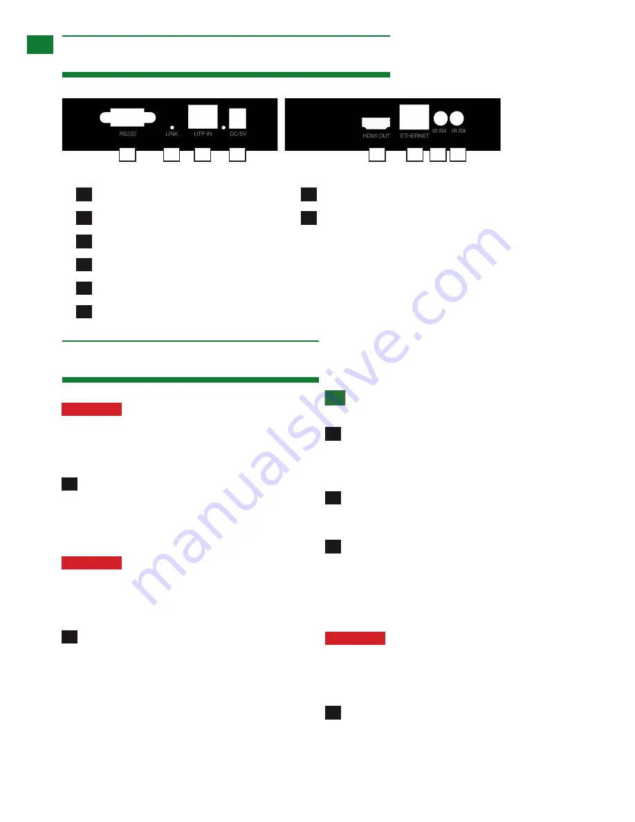
5iv. EX-1UTP-IR-100-EDID
Receiver
1
2
3
4
5
6
8
7
RS232 Port
LED HDBT Link Indicator (Lit for active)
UTP IN
DC 5V Power Input
HDMI OUT
TCP/IP Connector
3
4
5
IR TX Transmitter port
IR RX Receiver port
6. Connection & Operation
1
2
Attention:
Do Not Hotplug! - Please insert and
extract cables carefully with the power switched
off.
Connecting and disconnecting cables while the unit
is powered can damage circuitry.
Connect the HDMI source input (such as: Cable/
Satellite receiver, Blu-ray, games console, media device
etc.) to the HDMI IN port of the TRANSMITTER. Avoid
excessive bending of the HDMI cable and ensure
connectors are inserted firmly in all ports.
Attention:
We strongly recommend using the
supplied mounting brackets to secure both baluns.
Sudden movement of these devices can lead to
unnecessary service call outs and loss of picture/
sound due to stress on connections.
Position the IR emitter over the infrared receiving
area of the source device and fix with the adhesive
backing. You may need to adjust the location of the
emitter later to achieve the best results. Sometimes
moving the sensor to a different area on the source facia
can improve IR performance.
Insert the IR emitter 3.5mm jack into the IR TX port on
the TRANSMITTER.
Tip:
You can locate the infrared sensor by shining a
flashlight onto the facia of most devices.
For two-way IR (to control the display from the
source location) insert the IR receiver 3.5mm jack into the
IR RX port of¬ the TRANSMITTER. Then connect the IR
emitter to the IR TX port on the RECEIVER.
For transmission of LAN - connect an Ethernet
cable from your network router or switch to the Ethernet
port on the TRANSMITTER.
Connect a good quality, well terminated and tested
Cat5e/6 cable with RJ45 connectors from the UTP
OUT port of the TRANSMITTER to the UTP IN port of
the RECEIVER. Ensure connectors are pushed securely
into each port and the locking pin is engaged to prevent
loosening.
Attention:
UTP cable must be correctly
terminated to 568B standard at both ends (see
diagram). Inadequate cable quality or poor RJ45
termination leads to intermittent performance and
longer install times.
Connect your HDMI display (LED screen, Projector
etc.) to the HDMI OUT of the RECEIVER using a HDMI
cable.
6
2
3
6
4
1
7
5
8


