ba75695e03 10/2013
Operating manual
Turb 2000 Series:
Turb 2000 Turb 2020 Turb 2100 Turb 2110 Turb 2120
Process Turbidimeter
Страница 1: ...ba75695e03 10 2013 Operating manual Turb 2000 Series Turb 2000 Turb 2020 Turb 2100 Turb 2110 Turb 2120 Process Turbidimeter...
Страница 2: ...he latest version of the present operating manual can be found on the Internet under www WTW com Copyright Weilheim 2013 WTW GmbH Reprinting even as excerpts is only allowed with the explicit written...
Страница 3: ...libration standards 18 4 2 Calibration procedures 19 4 3 Calibration error 20 5 Instrument offset 21 5 1 Indexing calibration cuvettes 22 5 2 Restoring factory settings 22 6 Instrument configuration C...
Страница 4: ...ation 34 7 2 2 Modbus communication 34 7 3 Flow alarm 34 7 4 Flow controller 34 8 Error elimination 35 8 1 Trouble shooting 35 8 2 System FAIL message 35 8 3 Error messages 36 9 Routine maintenance 37...
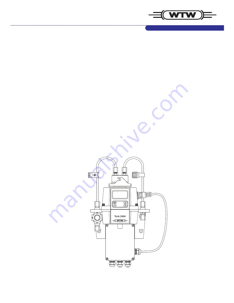
Страница 5: ...ht source Ultrasonic cleaning Turb 2000 White light No Turb 2020 White light Yes Turb 2100 IR No Turb 2110 IR No Turb 2120 IR Yes 1 2 Unpacking and inspection of the instrument and accessories The tab...
Страница 6: ...access code and offset mode In addition mode arrows 4 are used to indicate the current instrument operating mode AUTO normal operation CAL calibration and CONFIG configuration Figure 1 Display used in...
Страница 7: ...l well and the flow through cuvette This feature eliminates the need for a dry purge line The Turb 2000 series monitors the replaceable desiccant pouch condition continuously The LCD display will show...
Страница 8: ...er labels Note indicates notes or helpful hints that draw your attention to special features and give further clarification to the instructions Refer to the Table of Contents to easily find specific t...
Страница 9: ...ransport has been stored under adverse conditions for a lengthy period of time is visibly damaged no longer operates as described in this manual If you are in any doubt please contact the supplier of...
Страница 10: ...evel The installation dimensions of the instrument are given in figure 3 The following screws are required for installation M6 for the housing M4 for the field terminal box The Turb 2000 series is des...
Страница 11: ...valve 8 Drain tubing connection 9 Drain vent 10 Drain tubing connection 11 Sensor connection cable 12 Insert 13 Tubing not supplied 14 Nut The instrument is equipped to be plumbed using 4 75 mm 3 16...
Страница 12: ...or some high pressure systems where the vent hole continuously leaks a seal screw is provided which should be inserted into the vent hole and tightened The sensor drain tubing should be routed to a su...
Страница 13: ...the terminal box and are self descriptive see Figure 5 Please follow all local and government recommendations and methods for installation of electrical connections to and between the instrument and o...
Страница 14: ...ction Figure 5 shows the connections to be made The scope of delivery does not include a power cable If the instrument is to be used in the U S or Canada the power cord must be UL Listed CSA Certified...
Страница 15: ...vels that are not susceptible to electrical interferences This is why cable lengths up to 3000 ft can be implemented The last device on each bus may require terminating with a 120 ohm resistor to elim...
Страница 16: ...asured reading on the upper row of the display see illustration below 3 1 Routine measurement The following steps describe how to measure the turbidity of a sample using this instrument 1 Apply power...
Страница 17: ...code and then press the OK button to accept the first number of the code Now enter the second number in the code Proceed as with the first number followed by OK Then repeat the process for the third n...
Страница 18: ...ed using only a 10 NTU and a 0 02 NTU standard 1 0 NTU and 0 02 NTU for Turb 2110 To calibrate starting at the 10 NTU press the button to bypass the 1000 NTU and proceed to section 4 2 CALIBRATION PRO...
Страница 19: ...r information on indexing cuvettes 2 Remove the flow through unit 3 Insert the requested 1000 NTU standard 10 0 NTU for Turb 2110 Index the standard to the lowest value on the upper display see sectio...
Страница 20: ...ended that the measurement chamber be kept covered during the calibration period and that the flow through cuvette be replaced immediately after the calibration to prevent premature saturation of the...
Страница 21: ...he procedure may be stopped at this step However if the readings are substantially different but less that 1 NTU continue on in this procedure to utilize the offset option to improve the turbidity rea...
Страница 22: ...in future always insert the standard so that the pointer of the indexing ring faces forward Slowly rotate the standard back and forth about 5 to find the lowest point The standard is now indexed and...
Страница 23: ...side CONFIG is illuminated on the display Then press the OK button Note To exit the CONFIG mode press the MODE EXIT button 6 1 Selecting the output O P The first configuration selection is the O P The...
Страница 24: ...e 20 mA output level 20MA on the lower row of the LCD display Select the turbidity level to assign to the 20MA using the and buttons Once the desired level has been set press the OK button to accept i...
Страница 25: ...etting the baud rate and the address Select the correct baud rate 1200 2400 4800 9600 or 19200 for operation of the I O port by pressing the or buttons to change the displayed baud rate Press the OK b...
Страница 26: ...elays automatically change state when an internal system failure is detected Alarm set point The level at which an alarm activates is called the alarm set point On the instrument the alarm set point i...
Страница 27: ...Delay on The following display will appear to allow to select the number of seconds currently set for the delay on time The current selected number of seconds will be shown Select the desired number o...
Страница 28: ...e into the instrument to get to any mode other than AUTO The only code is 333 This code may not be changed See section 3 2 for more information on this security feature The security key icon will be v...
Страница 29: ...where monitoring of rapid changes is needed 6 10 Displayed resolution The instrument is equipped with the ability to display several levels of resolution The instrument can display up to four digits...
Страница 30: ...ctory set in NTU mode Make a selection using the and buttons then press the OK button 6 13 Ultrasonic cleaning Turb 2020 and 2120 This allows for a selection menu to turn off the ultrasonic cleaning f...
Страница 31: ...ctivate the alarms relays Can activate an alarm condition on the 4 20mA To activate the alarm relays when the desiccant fails select set one or both alarms to Error see section 6 5 CONFIGURING THE ALA...
Страница 32: ...similar to the previous menu This menu outputs a constant 20 mA while allowing for a small amount of adjustment The adjustment can be made using the and buttons The adjustment limits are 1000 counts o...
Страница 33: ...mA and alarms depending in the setting of the ERLV 4 20 mA and if an alarm is set up to Error If the correct cuvette is installed and the error is still posted try rotating the flow through unit slig...
Страница 34: ...attention character in ASCII or 3A Hex Byte 2 the address of the Turb 2000 instrument being queried Byte 3 4 CR LF or 0D 0A in hex The Turb 2000 will respond with The same attention character in ASCI...
Страница 35: ...played if an alarm is set and the threshold is exceeded An error indicates a failure or a problem that usually can be corrected by the operator These errors are listed in section 8 3 If any of these e...
Страница 36: ...led option Lower display shows FAIL System error Refer to section 8 1 8 2 Readings are higher than expected Bubbles in solution Ensure that the drain vent is open and is not obstructed See section 2 2...
Страница 37: ...t pouch 3 Sensor bottom For commissioning remove the transport protection square shaped plastic well with yellow flag from the sensor bottom The Turb 2000 continuously checks the condition of the desi...
Страница 38: ...ccant pouch is not effective e g because of an untight bag Figure 8 Humidity indicator To speed up the recognition by the instrument of the new desiccant it will be necessary to reset the instrument T...
Страница 39: ...9 kPa 0 069 bar or 1 psi Maximum water pressure Integral pressure regulator rated 1380 kPa 13 8 bar or 200 psi Flow rate 0 1 1 0 Liter min Operating temperature 1 C 50 C Wetted materials Nylon borosi...
Страница 40: ...1 0 10 0 NTU cleaning tissues and indexing rings ProCal Kit 600 056 RS 485 communication cable AK485 Turb DW 600 042 Ultrasound flow through cuvette for Turb 2020 and 2120 FTC US Turb DW 600 047 Flow...
Страница 41: ...Turb 2000 Series Mounting template ba75695e03 10 2013 41 12 Mounting template All dimensions are in mm inches...
Страница 42: ...Turb 2000 Series Mounting template 42 ba75695e03 10 2013...
Страница 43: ......
Страница 44: ...buildings factories and farms In more than 150 countries we have strong long standing relationships with customers who know us for our powerful combination of leading product brands and applications...