WTI CAS-161A Скачать руководство пользователя страница 8

Å

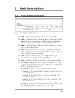
ACTIVE PORT Indicators:

These indicators are used

with the previously mentioned SECTION LEDs to indicate
the port currently connected to the Control port.
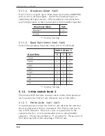
2.2.

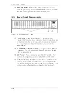
Back Panel Components

À

Input Ports 1 - 16:

Ports labeled 1 - 16 are 25-pin,

female, RS232 connectors. Optional RS422 connectors can
be factory installed to increase data transmission distance.
For a description of the port interface, please refer to
Appendix A.

Á

MODEM Port (Control Port):

A 25-pin, female, RS232

connector. For a description of the port interface, please
refer to Appendix A.

Â

AC Power:

Power connector and ON/OFF switch. The

unit can be jumper-selected for either 115 or 230 VAC.

Ã

SetUp Switches:

(Not Shown) Two banks of DIP switches

located on the underside of the unit. The SetUp Switches
are used to configure the prefix code, select baud rates and
parity, and set other features as described in Section 3.

2-2

CAS-161A User’s Guide

Figure 2.2: Instrument Back Panel

Содержание CAS-161A

Страница 1: ...WTI Part No 12114 Rev D CAS 161A Code Activated Switch User s Guide...

Страница 2: ......

Страница 3: ...Baud Rate Select Sw6 Sw8 3 2 3 1 2 SetUp Switch Bank 2 3 2 3 1 2 1 Prefix Code Sw1 Sw7 3 2 3 1 2 2 Parity Sw8 3 4 3 2 Connect Power Cable 3 4 3 3 Connect Data Cables 3 4 4 Port Selection 4 1 4 1 Sele...

Страница 4: ...List of Figures 2 1 Instrument Front Panel 2 1 2 2 Instrument Back Panel 2 2 A 1 RS232 Interface Apx 1 A 2 RS422 Interface Apx 1 C 1 Add On Module Installation Apx 3 ii Table of Contents...

Страница 5: ...ws data to pass between it and the Control port until the next Prefix Port Select code is detected The CAS 161A also features a Broadcast mode which enables the Control port to transmit to all ports O...

Страница 6: ...and enclosed in square brackets indicates a specific key For example Enter or Esc e g V Indicates a key combination used to invoke a command For example the text V Control V indicates the Ctrl key and...

Страница 7: ...t CTS Clear to Send Indicates a high RS232 signal received at pin 5 input of the Control port ALL Indicates Broadcast Mode is active all ports open SECTION Indicators When optional Add On Module s are...

Страница 8: ...n of the port interface please refer to Appendix A MODEM Port Control Port A 25 pin female RS232 connector For a description of the port interface please refer to Appendix A AC Power Power connector a...

Страница 9: ...fix Code Repetition Value Sw1 Sw4 The Prefix Code informs the unit that the next character will be a command In order to allow the unit to adapt to a variety of applications it is often useful to requ...

Страница 10: ...0 0 0 9600 1 0 0 4800 0 1 0 2400 1 1 0 1200 0 0 1 600 1 0 1 300 0 1 1 150 1 1 1 Factory Setting 3 1 2 SetUp Switch Bank 2 The bank of DIP switches located closest to the front panel are used to select...

Страница 11: ...F ON ON ON M CR OFF ON OFF OFF ON ON ON N SO ON OFF OFF OFF ON ON ON O SI OFF OFF OFF OFF ON ON ON P DLE ON ON ON ON OFF ON ON Q DC1 OFF ON ON ON OFF ON ON R DC2 ON OFF ON ON OFF ON ON S DC3 OFF OFF O...

Страница 12: ...t Data Cables Note Check to make certain all data cables are compatible Refer to the Appendix for a description of the interface 1 Make certain the power switch is OFF 2 Connect the data cables from t...

Страница 13: ...t below and find the letter representing the port you wish to connect to Module 1 Module 2 Module 3 Module 4 Port Code Port Code Port Code Port Code 1 17 P 33 49 p 2 A 18 Q 34 a 50 q 3 B 19 R 35 b 51...

Страница 14: ...time All data following the Port Select code is sent out the selected port including the next Prefix code Examples Assume the Prefix Code is V and the Prefix Code Repetition Value is 4 To connect to...

Страница 15: ...A Interface Description A 1 RS232 Ports Standard A 2 RS422 Ports Optional Note Handshake signals are not passed Pins 1 13 are open Apx 1 Figure A 1 RS232 Interface Figure A 2 RS422 Interface...

Страница 16: ...for a printable Prefix code B1 B7 on the chart shows 0 0 0 0 0 0 1 for Therefore Sw1 Sw6 should be ON and Sw7 OFF B7 0 0 0 0 1 1 1 1 B6 0 0 1 1 0 0 1 1 B5 0 1 0 1 0 1 0 1 Bits b4 b3 b2 b1 Col Row 0 1...

Страница 17: ...ea Add On Module w six wire power cable 2 ea Connecting Plates 1 ea Left Rack Mount Bracket Style 2 1 ea Right Rack Mount Bracket Style 2 18 ea 6 32 x 3 8 Screws To install Add On Modules refer to Fi...

Страница 18: ...On Module Ports Sw3 1 2 3 4 Section 2 17 32 On On Off Off Section 3 33 48 On Off On Off Section 4 49 64 On Off Off On 4 Repeat Step 3 to install any additional Add On Modules E and F Refer to the tabl...

Страница 19: ...Switched 2 3 4 and 5 Pins 6 and 8 of all Input ports follow Pin 6 of the Control port Power 90 VAC to 130 VAC jumper selectable 180 VAC to 260 VAC 47 to 450 Hz Ambient Temp 25 Operating Temp 0 C to 3...

Страница 20: ...ame and make of the unit its serial number and a description of its symptoms If the unit should need to be returned for factory repair it must be accompanied by a Return Authorization number from Cust...

Страница 21: ...pment does cause interference to radio or television reception which can be determined by turning the equipment off and on the user is encouraged to try to correct the interference by one or more of t...

Страница 22: ...spective companies Information and descriptions contained herein are the property of Western Telematic Inc Such information and descriptions may not be copied disseminated or distributed without the e...

Страница 23: ......

Страница 24: ...5 Sterling Irvine California 92618 949 586 9950 Toll Free 1 800 854 7226 Fax 949 583 9514 http www wti com...

Отзывы: