5-S10
L3130 · L3430 · L3830 · L4630 · L5030, WSM
BRAKES
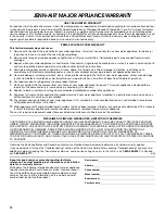
Brake Case
1. Disconnect the brake rod (1).
2. Place a block of wood (5) between floor seat (4) and lift arm (6)
to support the floor seat. (ROPS model)
3. Place the floor seat mounting bolts and nuts. (ROPS model)
4. Remove the floor seat support (3). (ROPS model)
5. Remove the fulcrum shaft (2) and disconnect the levers. (Left
side only)
6. Remove the brake case mounting screws and nuts.
7. Remove the brake case (7).
(When reassembling)
• Place the brake discs (10) so that the hole “A” of brake discs
should be overlapped 50 % or more.
• Apply liquid gasket (Three Bond 1208D or equivalent) to joint
face of the brake case and differential gear case.
• Be sure to apply the liquid gasket to a position.
• Apply grease to the steel ball seats. (Do not grease excessively.)
• Be sure to fix the brake cam (13) and cam plate (9).
• Before installing the brake case to the transmission case, install
the cam plate (9) to the transmission case.
W1015647
Brake Cam and Brake Cam Lever
1. Remove the brake cam mounting nut and remove the brake cam
(2) and brake cam lever (4).
(When reassembling)
• Apply grease to the O-ring (3) and take care not damage the O-
ring.
W1014346
Tightening torque
Brake case mounting
screw and nut
77.5 to 90.2 N·m
7.9 to 9.2 kgf·m
57.1 to 66.5 ft-lbs
Floor seat mounting bolt
and nut
196 to 225 N·m
20 to 23 kgf·m
145 to 166 ft-lbs
Brake case mounting stud
bolt
38.2 to 45.1 N·m
3.9 to 4.6 kgf·m
28.2 to 33.3 ft-lbs
(1) Brake Rod
(2) Fulcrum Shaft
(3) Floor Seat Support
(4) Floor Seat
(5) Block of Wood
(6) Lift Arm
(7) Brake Case
(8) Steel Ball
(9) Cam Plate
(10) Brake Disc
(11) Plate
(12) Brake Shaft
(13) Brake Cam
Tightening torque
Brake cam lever mounting
nut
62.8 to 72.5 N·m
6.4 to 7.4 kgf·m
46.3 to 53.5 ft-lbs
(1) Brake Case
(2) Brake Cam
(3) O-ring
(4) Brake Cam Lever
KiSC issued 02, 2007 A
Содержание L3130
Страница 1: ...WORKSHOP MANUAL TRACTOR L3130 L3430 L3830 L4630 L5030 KiSC issued 02 2007 A ...
Страница 7: ...5 L3130 L3430 L3830 L4630 L5030 WSM SAFETY INSTRUCTIONS KiSC issued 02 2007 A ...
Страница 8: ...6 L3130 L3430 L3830 L4630 L5030 WSM SAFETY INSTRUCTIONS KiSC issued 02 2007 A ...
Страница 9: ...7 L3130 L3430 L3830 L4630 L5030 WSM SAFETY INSTRUCTIONS KiSC issued 02 2007 A ...
Страница 17: ...15 L3130 L3430 L3830 L4630 L5030 WSM DIMENSIONS DIMENSIONS L3130 L3430 L3830 KiSC issued 02 2007 A ...
Страница 18: ...16 L3130 L3430 L3830 L4630 L5030 WSM DIMENSIONS L4630 L5030 KiSC issued 02 2007 A ...
Страница 19: ...G GENERAL KiSC issued 02 2007 A ...
Страница 81: ...1 ENGINE KiSC issued 02 2007 A ...
Страница 153: ...2 CLUTCH KiSC issued 02 2007 A ...
Страница 154: ...CONTENTS MECHANISM 1 FEATURE 2 M1 KiSC issued 02 2007 A ...
Страница 173: ...3 TRANSMISSION KiSC issued 02 2007 A ...
Страница 223: ...3 S6 L3130 L3430 L3830 L4630 L5030 WSM TRANSMISSION Error Message Does not Indicate on LCD KiSC issued 02 2007 A ...
Страница 224: ...3 S7 L3130 L3430 L3830 L4630 L5030 WSM TRANSMISSION KiSC issued 02 2007 A ...
Страница 225: ...3 S8 L3130 L3430 L3830 L4630 L5030 WSM TRANSMISSION 3 HST SYSTEM KiSC issued 02 2007 A ...
Страница 226: ...3 S9 L3130 L3430 L3830 L4630 L5030 WSM TRANSMISSION KiSC issued 02 2007 A ...
Страница 335: ...4 REAR AXLE KiSC issued 02 2007 A ...
Страница 336: ...CONTENTS MECHANISM 1 STRUCTURE 4 M1 KiSC issued 02 2007 A ...
Страница 346: ...5 BRAKES KiSC issued 02 2007 A ...
Страница 347: ...CONTENTS MECHANISM 1 LINKAGE 5 M1 2 OPERATION 5 M2 KiSC issued 02 2007 A ...
Страница 362: ...6 FRONT AXLE KiSC issued 02 2007 A ...
Страница 363: ...CONTENTS MECHANISM 1 STRUCTURE 6 M1 KiSC issued 02 2007 A ...
Страница 387: ...7 STEERING KiSC issued 02 2007 A ...
Страница 414: ...8 HYDRAULIC SYSTEM KiSC issued 02 2007 A ...
Страница 463: ...9 ELECTRICAL SYSTEM KiSC issued 02 2007 A ...
Страница 556: ...10 CABIN KiSC issued 02 2007 A ...
Страница 569: ...10 S3 L3130 L3430 L3830 L4630 L5030 WSM CABIN AIR CONDITIONING SYSTEM Continued KiSC issued 02 2007 A ...
Страница 570: ...10 S4 L3130 L3430 L3830 L4630 L5030 WSM CABIN KiSC issued 02 2007 A ...