6
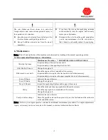
Tighten slightly to hold handle in place. Insert upper
bolts and washers into remaining holes in lower
handle and their respective holes on snow thrower.
Tighten all four bolts. (FIG 2)
FIG 2
2.4 Upper Handle Installation
1
RH and LH Upper Handles
4
Carriage Bolt M8 x 45 (XSZ56-1-15)
4
Flat Washer M8
4
Lock Nut M8
Procedure
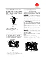
2.4.1
Assemble the RH and LH upper handles to the
lower handle with (4) M8×45 carriage bolts, M8
washers, and M8 nuts.
(
FIG 3
)
FIG 3
2.5 Speed Control Rod Installation
1
Speed Control Rod Assembly
2
Flat Washer M10
1
Hair Pin Cotter Pin
Procedure
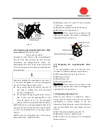
2.5.1
After completing handle assembly installation,
install the speed control rod assembly. The upper
control panel side of the Speed Control Rod Assembly
has been pre-assembled. Ensure that rod swivel, cotter
pin, and pre-set adjustment nut are in place. Attach the
lower end of rod assembly to the speed selector
control rod assembly located at the back center of the
engine support frame; insert rod into hole provided
and install flat washers and cotter pin. (FIG 1
)
2.6 Discharge Chute Assembly Installation
1
Discharge Chute Assembly
4
Hex Hd Bolt M6 x 20
2
Hex Hd Bolt M6 x 16
6
Lock Nut M6
1
Flat Washer M6
1
Hair pin cotter pin
Procedure
2.6.1
Place discharge chute assembly on top of
opening of Auger/Impeller housing. Attach connector
plate of gear assembly weldment to connector plate of
bottom chute mounting bracket weldment with (4)
M6x20 bolts and locknuts; tighten.
2.6.2
Attach chute control connecting rod (chute gear
assembly) to discharge chute connecting rod (handle
assembly) by using (2) M6x16 bolts and locknuts;
tighten.
2.6.3
Remove set screw from top of chute gear
assembly cover and remove cover. Ensure that
discharge chute control cable is inserted in hole
provided and seated in slot. Place cover back in place
and tighten set screw. Also, ensure that control handle
side of cable is inserted in hole provided and security
nuts tightened.
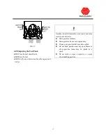
2.6.4
Thread deflector control lever cable assembly
through cable support wires. Connect eyelet of
deflector control lever cable to stud located on
deflector; add washer and insert hairpin. Insert cable
into slot on side of chute and tighten security nuts.
Ensure that the control lever end of cable on handle
assembly is inserted into hole provided and security
nuts tightened. (FIG 4)
Содержание WS2690BSE
Страница 2: ......
Страница 13: ...8 3 Product Overview FIG 5 Refer to engine instruction book FIG 7 FIG 6 ...
Страница 27: ......


