13
WDPre3 Kit Assembly Instructions
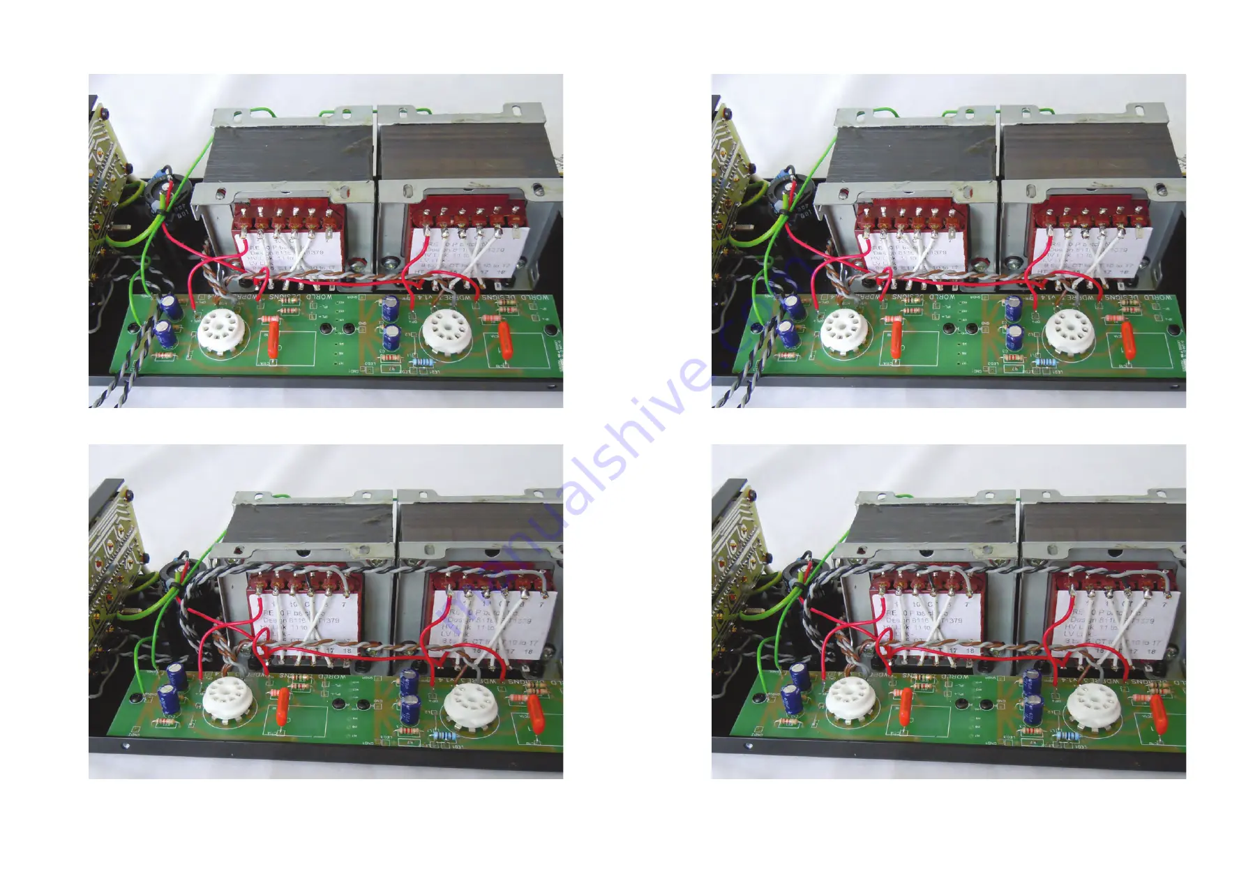
Fig. 12
Heater Wiring
Fig. 13
Output Wiring
Страница 1: ...ER THE PHONO SOCKETS AT THIS STAGE FITTING THE RELAY SWITCH BOARD Fig 9 Input Selector Switch Fig 9 10 Holding the shaft of the switch in a small vice or mole grips cut the shaft of the input selector...
Страница 2: ...WDPre3 Kit Assembly Instructions FITTING THE PRE3 PCB Fig 10 Fig 10 Transformer Screen Links Fig 11 11 Fit the main PCB to the case with the IP and IP terminals closest to the front panel Fit M3 x 12...
Страница 3: ...m wires to the transformer closest to the rear of the chassis Fig 11 Fig 11 HT Wiring Fig 12 Fig 13 12 WDPre3 Kit Assembly Instructions Using a short length of red cable link the OP terminal on the PC...
Страница 4: ...13 WDPre3 Kit Assembly Instructions Fig 12 Heater Wiring Fig 13 Output Wiring 13 WDPre3 Kit Assembly Instructions Fig 12 Heater Wiring Fig 13 Output Wiring...
Страница 5: ...3 Kit Assembly Instructions WIRING THE INPUTS AND VOLUME CONTROL Fig 14 Potentiometer Wiring Fig 14 Take 275mm Blue twin core screened cable cut back the outer insulation AND the screen braid to appro...
Страница 6: ...ing to the fascia Proceed to Constructing the Power Cables and Testing the Amplifier WIRING THE LED 15 Taking the 60mm signal cable from the potentiometer cut to length and trim back the outer insulat...
Страница 7: ...Heater ve 2 HT 3 Green Y Ground 4 Heater ve Fig 16 Power Plug and Socket Connections Fig 16 Fig 17 16 The power cables for the WDPre3 and WDPhono3 are assembled from the cable binder line sockets and...
Страница 8: ...17 WDPre3 Kit Assembly Instructions Fig 17 Binder Line Plug and Socket Construction 17 WDPre3 Kit Assembly Instructions Fig 17 Binder Line Plug and Socket Construction...
Страница 9: ...Heater Pin 3 HT Pin 2 HT Pin 4 Heater 380V to 420V DC 5 9V to 6 7V DC Fig 18 Power Socket Voltages 18 Before connecting the power supply it is good practice to check all the wiring component position...