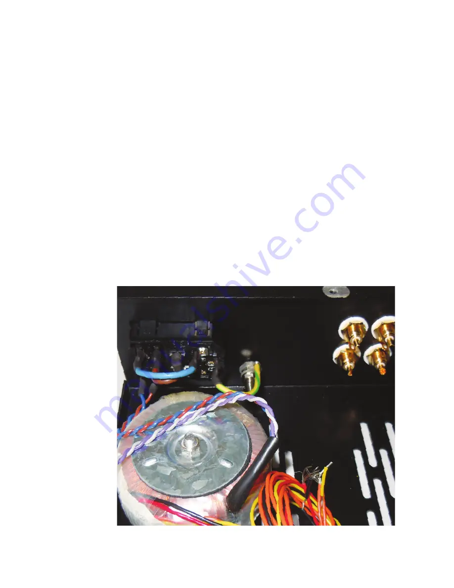
Fig. 5
IEC Input Wiring
WDHD3S Kit Assembly Instructions
6
Select the AC voltage for the power transformer to suit your AC
mains supply voltage as follows:
220
-
240V
: Solder the grey and purple primary wires together
and insulate the joint. Twist these wires together and coil them
neatly out of the way. Twist the blue and brown wires together,
pass them through the piercing in the chassis, and solder blue
to pin 3 and brown to pin 2 of the IEC input. These joints
should be insulated with heat
-
shrink sleeving.
100
-
120V
: Twist all the primary wires together, pass them
through the piercing in the chassis, and solder the blue and
purple wires to pin 3 and the brown and grey wires to pin 2 of
the IEC input. These joints should be insulated with heat
-
shrink
sleeving.
Making sure that the power switch is positioned nearest the
outside of the chassis, fit the IEC input into the hole in the
chassis and snap it into place. The lugs should provide a secure
fix. Connect the Green / Yellow wire from Blade 7 to the chassis
Earth Post.
NB: The fuse is held in a pull
-
out tray in the IEC input
-
you
may wish to fit it now. Please note the precautions on fuse
rating in the Safety Warning at the beginning of the manual.
Fig. 5
Fig. 5
IEC Input Wiring
WDHD3S Kit Assembly Instructions
6
Select the AC voltage for the power transformer to suit your AC
mains supply voltage as follows:
220
-
240V
: Solder the grey and purple primary wires together
and insulate the joint. Twist these wires together and coil them
neatly out of the way. Twist the blue and brown wires together,
pass them through the piercing in the chassis, and solder blue
to pin 3 and brown to pin 2 of the IEC input. These joints
should be insulated with heat
-
shrink sleeving.
100
-
120V
: Twist all the primary wires together, pass them
through the piercing in the chassis, and solder the blue and
purple wires to pin 3 and the brown and grey wires to pin 2 of
the IEC input. These joints should be insulated with heat
-
shrink
sleeving.
Making sure that the power switch is positioned nearest the
outside of the chassis, fit the IEC input into the hole in the
chassis and snap it into place. The lugs should provide a secure
fix. Connect the Green / Yellow wire from Blade 7 to the chassis
Earth Post.
NB: The fuse is held in a pull
-
out tray in the IEC input
-
you
may wish to fit it now. Please note the precautions on fuse
rating in the Safety Warning at the beginning of the manual.
Fig. 5


