Worcester Greenstar 12i System ErP Скачать руководство пользователя страница 34

SERVICE AND SPARES

6 720 804 532 (2012/09)

34

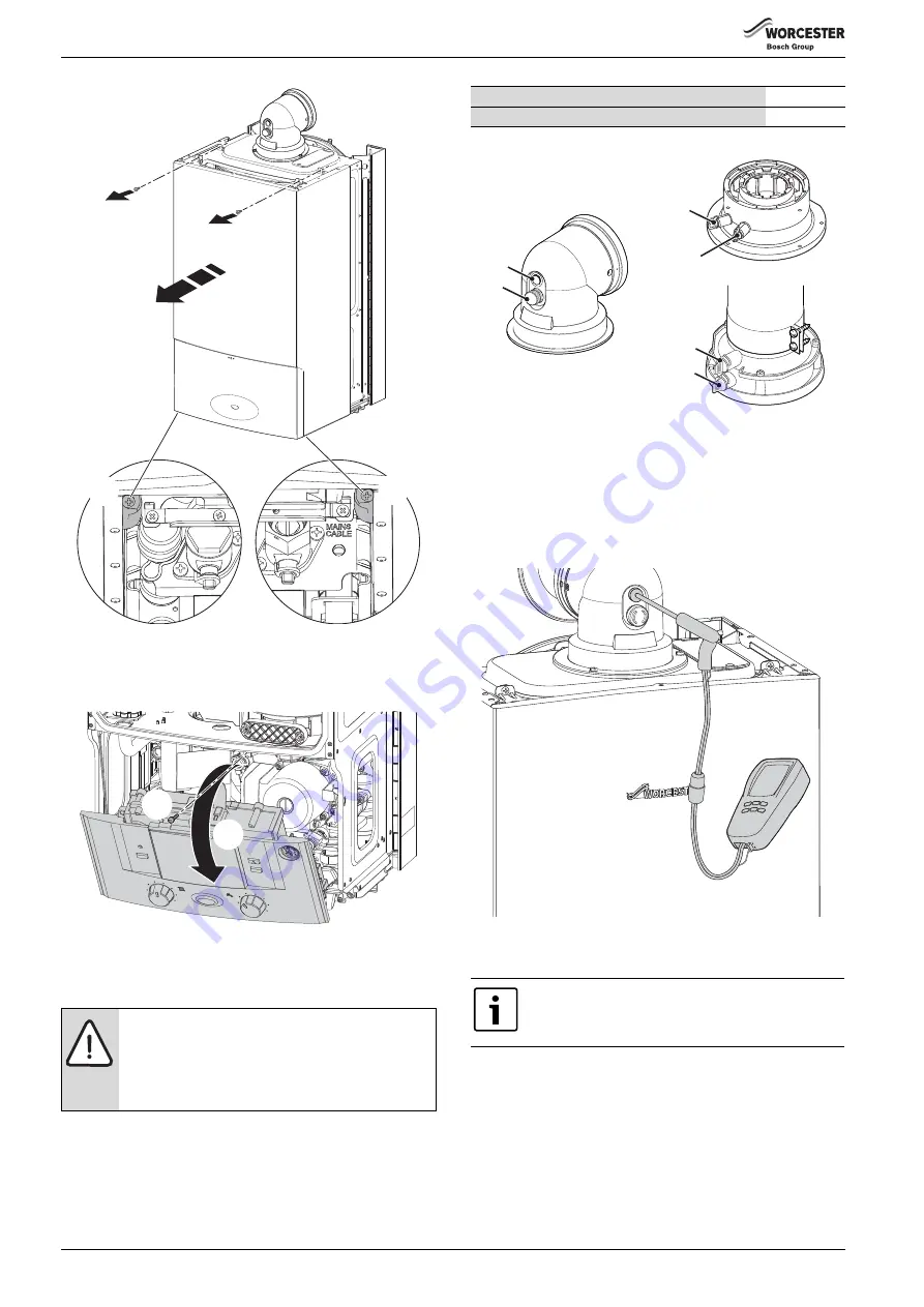
Fig. 70 Remove outer case

2. Lowering boiler control to the service position:

– Remove screw (1) securing the control panel.
– Pull the panel (2) forward into the service position.

Fig. 71 Moving control panel into the service position

6.2

CHECK THE GAS INLET PRESSURE

Refer to section  5.5.1 for checking the gas inlet pressure.

6.3

CHECKING FLUE INTEGRITY

The integrity of the flue system and performance of the boiler can be 
checked via the flue turret sample points.

Fig. 72 Flue test points

▶ With the boiler case on and the boiler running at maximum.
▶ Insert the analyser probe into the air intake test point.
▶ Allow the readings to stabilise and check that:

– O

is equal to, or greater than 20.6%

– CO

is less than 0.2%

▶ If the readings are outside these limits then this indicates that there is 

a problem with the flue system or combustion circuit.

Fig. 73 Flue integrity test

6.4

FAN PRESSURE TEST

SETTING THE BOILER TO MAXIMUM

1. Press and HOLD service button for more than 10 seconds
2. Set the Central Heating temperature to maximum.

– The service button will illuminate continually and the blue power 

indicator will pulse 5 times.

– The boiler will stay in this mode for 15 minutes unless the service 

button is pressed again.

NOTICE: 

▶ Ensure that the gas inlet pressure is satisfactory with 

all other gas appliances working.

▶ Do not continue with the other checks if the correct 

gas inlet pressure can not be achieved.

1.

1.

2.

2.

6720643895-57.1W

o

1.

2.

6720644743-18.1Wo

Flue gas sample point

1

Air inlet sample point

2

Table 19 Key to figure 72

This test is to 

determine if the heat cell requires 

cleaning/attention.

2

1

2

2

1

1

6720643895-67.1Wo

6720643895-104.1W

o

Содержание Greenstar 12i System ErP

Страница 1: ...L HEATING SYSTEMS AND INDIRECTLY FED DOMESTIC HOT WATER 6 720 804 532 2012 09 The appliance is for use with Natural Gas or L P G Cat II 2H3P type C13 C33 C53 Model GC Number Natural Gas 12i System 41...

Страница 2: ...OMMISSIONING 29 5 1 Pre Commissioning checks 29 5 2 Filling the system 30 5 3 Water treatment 30 5 4 Starting the appliance 31 5 5 Commissioning 31 5 5 1 Checking the gas inlet pressure 31 5 5 2 Check...

Страница 3: ...he start of a warning indicate the type and seriousness of the ensuing risk if measures to prevent the risk are not taken This symbol indicates important information where there is no risk to people o...

Страница 4: ...lding Regulations Building Standards Scotland Consolidation Building Regulations Northern Ireland local water by laws Health Safety Document 635 The Electricity at Work Regulations 1989 and any other...

Страница 5: ...of case front 1 700mm 400mm 330mm Depth to wall When fitted to wall frame 6 6720644743 01 3Wo STANDARD PACKAGE 1 Wall hung gas fired condensing system boiler for central heating and hot water 2 Wall...

Страница 6: ...37 55 38 CO2 level at max rated heat output after 30 min 9 65 9 8 9 8 9 8 11 0 11 0 11 0 11 0 CO2 level at min rated heat output after 30 min 8 65 9 2 9 2 9 2 10 5 10 5 10 5 10 5 NOx class 5 5 4 5 5 5...

Страница 7: ...APPLIANCE INFORMATION 6 720 804 532 2012 09 7 2 3 LAYOUT Fig 1 Main boiler components 6720804532 03 1Wo 1 2 30 29 28 27 26 10 14 12 11 13 15 16 25 23 24 22 21 20 19 18 17 3 4 5 6 7 8 9...

Страница 8: ...m heat exchanger 11 Right side hand hold for lifting boiler 33 Expansion vessel hose connection point 12 Diverter valve assembly body 34 Auto air vent 13 Diverter valve actuator stepper motor blank 35...

Страница 9: ...hine to aid the cleansing procedure in some circumstances Close the drain cocks and refill with fresh water and a suitable inhibitor Vent any air from the boiler and system 1 Burner ON indicator light...

Страница 10: ...re up to 3 bar Radiator valves should conform to BS2767 10 All other valves should conform to BS1010 Thermostatic radiator valves TRV s must be used on all radiators within the sleeping accommodation...

Страница 11: ...boiler is fitted with its own internal bypass 1 Diverter Zone valve 2 Radiator valve flow 3 Lock shield valve return 4 Bypass NOTICE A drain cock should be fitted at the lowest point of the heating ci...

Страница 12: ...ate pump disposal 3 4 2 EXTERNAL CONNECTIONS Ifnootherdischargemethodispossiblethentheuseofanexternallyrun condensate drainage pipe terminating at a suitable foul water discharge point or purpose desi...

Страница 13: ...NDENSATE SOAK AWAY The condensate drainage pipe may be run above or below the ground tothesoakaway Theexamplesshownonthispagerunaboveground The soak away must use a 100mm plastic tube with two rows of...

Страница 14: ...long as the minimum clearances around the boiler are maintained Ideally storage should be below the boiler where the boiler is mounted in the upper part of the cupboard whilst maintaining the clearan...

Страница 15: ...ent minimum clearances are Side Above Below Front to removable door 400 170 approx 30 above the elbow 200 100 Table 11 Minimum unventilated compartment clearances If Side Clearances are Reduced millim...

Страница 16: ...e bends should be viewable from both directions NOTICE Effective flue lengths each 90 bend used is equivalent to 2 metres of straight flue each 45 bend used is equivalent to 1 metre of straight flue P...

Страница 17: ...PRE INSTALLATION 6 720 804 532 2012 09 17 350 mm 570 mm 130 mm Min Flat roof 300 mm 500 mm Pitched roof 2 3 4 5 6 10 9 8 7 1 6720643895 12 1Wo...

Страница 18: ...600mm to room sealed flue or 1 500 to an open flue 15 200mm below eaves and 75mm below gutters pipe and drains 16 The dimension below eaves balconies and car ports can be reduced to 25mm as long as th...

Страница 19: ...t point of the balcony or overhang 9 1 200mm from an opening in a car port on the same wall e g door or window leading into the dwelling 10 600mm distance to a surface facing a terminal unless it will...

Страница 20: ...rotective clothing footwear gloves and safety goggles must be worn as appropriate FIXING THE WALL MOUNTING FRAME Theboilertemplateshowstherelativepositionsoftheflueandthetop and bottom fixing of the m...

Страница 21: ...inner sleeve 2 still in place gently lay the boiler on its back Theboilerwilllieatanangletothefloortoallowtheboileroutercasing 5 to be removed The inner sleeve 2 opens as shown in figure 28 Remove th...

Страница 22: ...mm insulated pipe Fig 30 Condensate drain pipe work detail PREPARING THE WALL FRAME Fit sealing washers to service valves before hanging boiler Fig 31 Sealing washers 1 Pull the extended tab lever for...

Страница 23: ...ON To connect the expansion vessel flexible pipe to the hydraulic manifold situated to the left of the pump Removeanddiscardtheplasticcapfromtheexpansionvesselflexible pipe 1 Refer to figure 35 releas...

Страница 24: ...Fig 38 Standard telescopic flue Extend tube 1 by withdrawing from tube 2 to achieve the flue length required between 350 570mm Secure with screw provided and seal joint with the aluminium tape suppli...

Страница 25: ...y and the components are pushed fully home The flue is set at an angle of 3 or 52mm per metre length Support theflueatapproximatelyonemetreintervals andatachange of direction use suitable brackets and...

Страница 26: ...on NOTICE Outlet position The flue terminal outlet position must follow those stated in the relevant appliance instruction manual When redirecting the flue discharge the outlet terminal must be at lea...

Страница 27: ...screw securing the control panel 2 Lower the control panel into the horizontal service position Fig 51 Moving control panel into the service position 1 Refer to figure 52 and unscrew the three screws...

Страница 28: ...the living area is more than 70 of the total useable floor area Then this type of dwelling can be controlled as one zone An alternative would be individual electronically controlled TRVs Hot water sup...

Страница 29: ...discharge pipe 1 has been connected to the syphon and condensate outlet pipe NOTICE Externaldivertervalve s andallother230Vpartsare not supplied with the boiler A fascia mounted programmer timer cann...

Страница 30: ...THAT THE SYSTEM HAS BEEN CLEANED AS ON PAGE 9 OF THESE INSTRUCTIONS FLUSHING Central Heating Switch off the boiler Open all drain cocks and drain the system while the appliance is hot Close drain coc...

Страница 31: ...l Heating temperature to maximum The service button will illuminate continually and the blue power indicator will pulse five times Check the gas supply working pressure at the gas valve conforms to va...

Страница 32: ...urntonormaloperation after 15 minutes Close the gas isolation valve Remove the manometer Re seal the screw in the gas inlet pressure test point Open the gas isolation valve Ensure that there are no ga...

Страница 33: ...ditionoftheappliancewhentestedbyfullyqualified engineers The service interval record sheet at the rear of these instructions must be completed after each service INSPECTION 1 Check that the terminal a...

Страница 34: ...n 0 2 If the readingsare outside these limits thenthis indicates that there is a problem with the flue system or combustion circuit Fig 73 Flue integrity test 6 4 FAN PRESSURE TEST SETTING THE BOILER...

Страница 35: ...5 FLUE GAS ANALYSIS COMBUSTION TEST Connect the flue gas analyser to the flue gas sampling point as shown in the figure below Run the boiler at maximum output for at least 10 minutes Check the CO CO2...

Страница 36: ...ve NOTICE THE SETTING OF THE GAS RATIO MUST BE CARRIED OUT BY A COMPETENT PERSON SETTING OF THE GAS RATIO MUST NOT BE ATTEMPTED UNLESS THE PERSON CARRYING OUT THE TEST IS EQUIPPED WITH A COMBUSTION AN...

Страница 37: ...figure 84 1 Remove clamping plate 2 Remove spark flame electrode assembly and seal from the top of the heat exchanger 3 Remove burner Fig 84 Burner removal Checking and cleaning the electrode assembl...

Страница 38: ...d ensure that the seal is correctly fitted Check the syphon unit is clean before refitting to boiler Reassemble and check combustion as stated in SETTING THE AIR GAS RATIO section on page 36 Fig 87 Cl...

Страница 39: ...he shoulder Fig 89 Primary sensor and overheat thermostat 6 8 4 FLUE OVERHEAT THERMOSTAT WITH GROMMET To remove and replace the thermostat either Usingasmallterminalscrewdriver prisethethermostatandgr...

Страница 40: ...on 6 8 7 AIR GAS MANIFOLD AND FAN ASSEMBLY Remove electrical connector and earth wire the from fan Removewireclipfromgasvalveoutletthenpullgaspipefreefromthe gas valve see figure 93 Toremove thefollow...

Страница 41: ...AP VALVE ASSEMBLY 1 Twist the mounting flange clockwise to release 2 Pull mounting flange off the flap valve assembly 3 Pull rubber flap off flap valve assembly To replace the flap valve Press the two...

Страница 42: ...ust connector down Fig 101 Upper exhaust assembly 1 Refer to figure 102 and release the clip 2 Move the lower exhaust connector up Remove the complete exhaust assembly Fig 102 Release lower exhaust co...

Страница 43: ...trical connections from the control 1 Remove five screws retaining the rear panel of the control 2 Remove the rear panel Fig 108 PCB access REFITTING THE CONTROL BOARD COVER Ensure that all wires are...

Страница 44: ...on upwards 2 Slide the control support bracket to the left Fig 111 Control unit release Remove appropriate cable restraints from the new control unit Fit control unit to the boiler Ensuring the contro...

Страница 45: ...ilable Fig 114 Diverter valve and motor 6 8 17 DIVERTER VALVE IF FITTED Ensure the appliance has been fully drained Disconnect the electrical connector from the diverter valve motor Remove the diverte...

Страница 46: ...e and pump Undo the nuts securing the copper water pipes to the manifold there is no need to remove the gas pipe 1 Release the spring clips securing these water pipes to the plastic housing and remove...

Страница 47: ...of the flue is required If this clearance is not available then the boiler will need to be removed from the mounting frame to gain access to the expansion vessel Alternatively a second vessel of at le...

Страница 48: ...connection to the pump manifold Carefully lift the boiler off the mounting frame 1 Remove the expansion vessel retaining screw 2 Lift the expansion off the cross beam 3 Pull the expansion vessel towa...

Страница 49: ...y pass valve 8 716 106 434 0 GC No H02 532 Pressure gauge 8 718 224 344 0 Flow temperature sensor NTC 8 716 106 688 0 GC No H26 542 High limit stat 8 707 206 196 0 GC No H26 584 Fusing element set 8 7...

Страница 50: ...that there is no permanent live at ST10 LR from another source Boiler not operating duringhotwaterdemand CH ok Ensure cold inlet DHW outlet are correctly piped i e are not crossed piped If the optiona...

Страница 51: ...PERATURE CONTROL Red Neutral Supply 230V EXTERNAL CONTROLS OPTION WORCESTER 24V CONTROLS OPTION PLUG IN POINT under blanking cover on fascia Live Supply Live Return Neutral Live Orange Blue Yellow Gre...

Страница 52: ...T 10 second stabilisation period Fan modulation to achieve set temperature 40 82 C END OF BOILER DEMAND Gas valve OFF Pump run 3 minutes Fan run 30 seconds Over temperature shut down if water tempera...

Страница 53: ...period Internal boiler temperature rises above 12 C Central heating demand switches off Pump switches off after a 3 minute overrun period Central heating demand is activated Pump runs for 3 minutes to...

Страница 54: ...ffect the customer s statutory rights If yes and if required by the manufacturer has a water scale reducer been tted CONDENSING BOILERS ONLY The condensate drain has been installed in accordance with...

Страница 55: ...er Name Company Name Telephone No Gas Safe Register No Comments Signature Date Engineer Name Company Name Telephone No Gas Safe Register No Comments Signature Date Engineer Name Company Name Telephone...

Страница 56: ...Worcester Bosch Group is a brand name of Bosch Thermotechnology Ltd worcester bosch co uk 6 720 804 532 2012 09 WORCESTER BOSCH GROUP TECHNICAL SUPPORT 0844 892 3366 APPOINTMENTS 0844 892 3000 SPARES...

Отзывы: