ProAct II Actuator/Driver
Manual 04176
20
Woodward
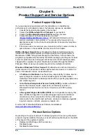
Chapter 4.
Troubleshooting
Improper engine operation is often the result of factors other than governor
operation. This chapter gives tips about engine problems which can resemble
governor problems. Make sure the engine is operating correctly before making
any changes in the governor.
Attempting to correct engine or load problems with untimely governor adjustment
can make problems worse.
If possible, isolate the governor from the engine to determine if the problem is
with the governor and not with the engine or the load on the engine.
Governor faults are usually caused by installation problems or the linkage
between the actuator and the engine. Carefully review all the wiring connections,
the power supply, and the linkage before making any adjustments to the actuator
or driver. Always check the fuel-control linkage from stop to stop as if the
actuator were moving it. The linkage must move freely without friction and
without backlash. Some fuel controls will present problems at particular fuel or
rack position because of a hesitation or binding in the linkage.
Fuel supply and injector conditions can also present problems which resemble
governor problems.
On spark-ignited engines, distributor, coil, points, and timing problems can all
cause improper operations which may resemble faulty governor control.
Linkage and Actuator Stroke
Use as much of the 75 degrees of actuator stroke as possible. Carefully follow
the guidelines in the Actuator Installation section of Chapter 2 in making linkage
arrangements. Using less than optimum actuator movement will make stability
more difficult, and will make the actuator more sensitive to external loading
forces and friction.
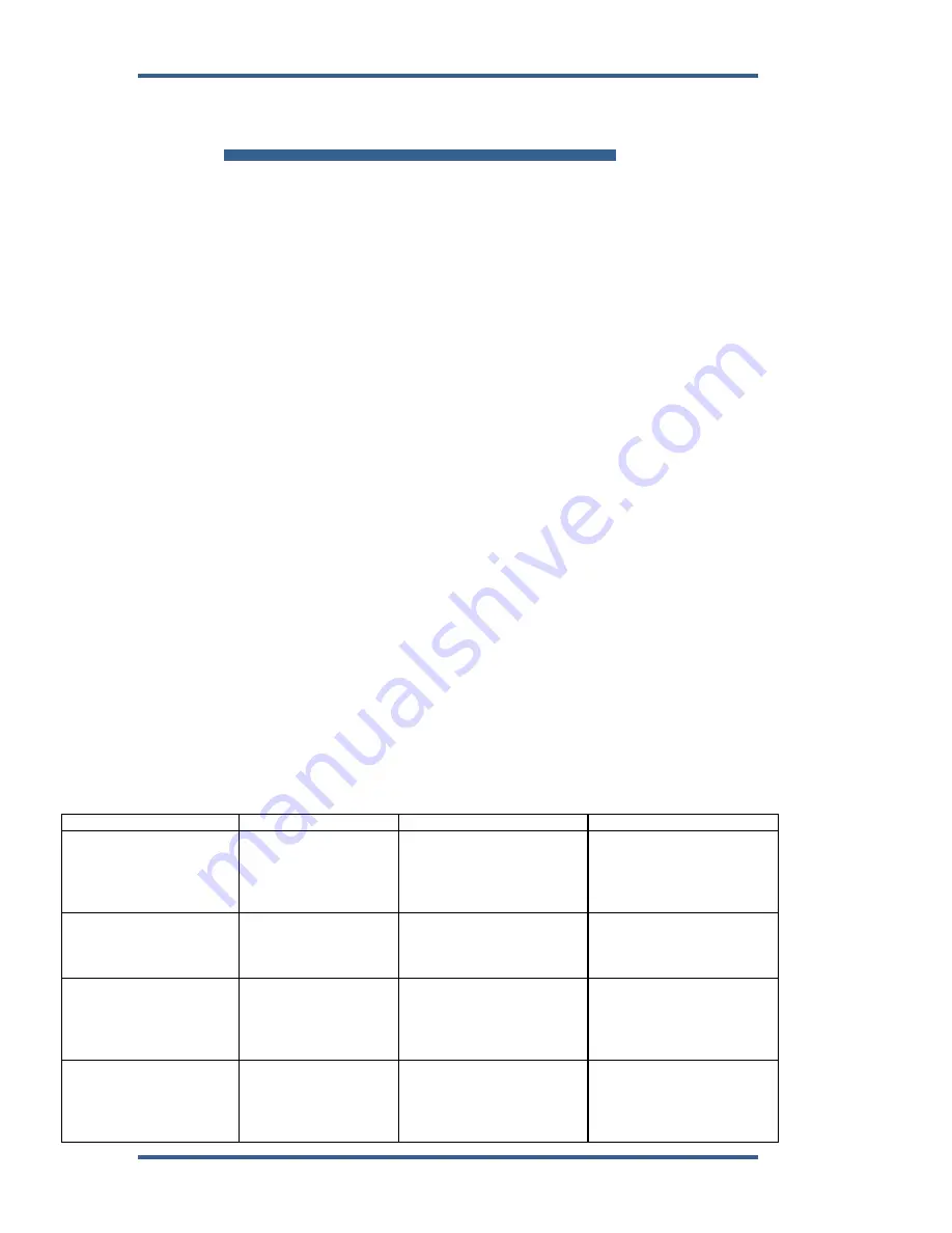
Possible problems with driver-actuator system include:
Symptom
Possible Cause
Possible Fix 1
Possible Fix 2
Actuator drives opposite
direction than the
command signal directs.
Actuator drive and
position feedback
signals are connected
incorrectly.
Actuator drive wires and
position feedback (both)
may be connected in the
reverse polarity. Check
wiring for proper polarity.
Actuator drives into max
stop with a command to
min fuel applied.
Actuator drive or
position feedback
signals are connected
incorrectly.
Actuator drive wires may
be connected in the
reverse polarity. Check
wiring for proper polarity.
Actuator position feedback
input may be connected in
the reverse polarity. Check
wiring for proper polarity.
Actuator drives into min
stop with a command to
mid fuel (or some other
non-stop command)
applied.
Position command
signal is not being
received correctly.
Position command input
leads may be connected in
wrong polarity. Check
wiring for proper polarity.
Position command input
may have poor connection
to input signal. Check
wiring for good connection.
Actuator and control
system do not respond—
all voltage outputs are 0
V.
Actuator and driver is
not receiving power.
Input power leads may be
connected in wrong
polarity. Check wiring for
proper polarity.
Input power leads may
have poor connection to
b or battery –.
Check wiring for good
connection.

