Woodward easYlite-200 Скачать руководство пользователя страница 22

4  Configuration

The easyLite-200 device is configured via the ToolKit software.

This may be done both in the respective 100-/1000-series easY‐

gen's ToolKit configuration screens (LED message assignment)

and in the specific easYlite-200 ToolKit configuration. The following

subchapters provide a more detailed account of the configuration

steps.

4.1  easYgen: LED Configuration and Labelling

The signal assignment/label content can be configured via 100-/

1000-series easYgen's software ToolKit. In order to do this, please

go to 

“Parameter 

è

  Configure application 

è

 Configure Ext. LED”.

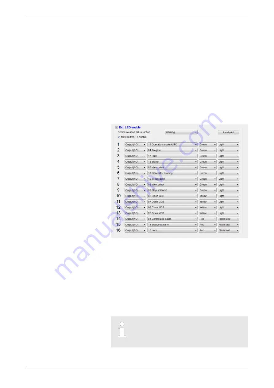
The following screen appears as in Fig. 10 below:

Fig. 10: Label configuration in ToolKit
In the topmost drop-down list the user can select one of five

actions, depending on the actual easYgen device, to be taken

upon communication failure (Warning, Shutdown, Trip and Stop,

Trip, Indication).
Below are the sixteen rows for the configurable signals, corre‐

sponding to easYlite-200's LEDs. In the first column, the output

status can be selected (normally closed or normally open). In the

second column, one of the parameters is selected to be associated

with the specific LED. The drop-down menu in the third column

allows to specify the light color (red, green or yellow), while in the

last one - the light output variation (continuous light, flashing fast,

flashing slow).

For the actual list and descriptions of warnings/

alarms/status messages assigned, see documen‐

tation of the respective 100-/1000-series easYgen

device.

General information

Configuration

easYgen: LED Configuration a...

37903A

easYgen Expansion Module | LED Lamp Expansion Module

22

Содержание easYlite-200

Страница 1: ...easYlite 200 Manual LED Lamp Expansion Module easYgen Expansion Module Software Version 1 0 37903A...

Страница 2: ...l Technical Manual Woodward GmbH Handwerkstrasse 29 70565 Stuttgart Germany Telephone 49 0 711 789 54 510 Fax 49 0 711 789 54 101 E mail stgt info woodward com Internet http www woodward com 37903A ea...

Страница 3: ...LED display module with 16 programmable alarm warning and status lamps for which three colors red green yellow can be chosen The data collected by easYgen series controllers are transmitted to the ea...

Страница 4: ...n module All screwable terminal connectors are delivered with plug and jack n Clamp fastener installation material 4x n Installation Procedure Supplement paper with links to the latest edition of Tech...

Страница 5: ...Display and Status Indicators 15 3 Installation 16 3 1 Installation 16 3 2 Terminal allocation 18 3 3 Wiring diagram 19 3 4 Power Supply 19 3 5 Relay outputs 20 3 6 Interfaces 21 4 Configuration 22 4...

Страница 6: ...8 Appendix 31 9 Index 32 Table of contents 37903A easYgen Expansion Module LED Lamp Expansion Module 6...

Страница 7: ...ation that could cause death or severe injuries if not avoided WARNING This combination of symbol and signal word indi cates a possibly dangerous situation that could cause death or severe injuries if...

Страница 8: ...consideration of applicable guidelines and regulations the current and known state of the art as well as our many years of in house experience Woodward assumes no liability for dam ages due to n Fail...

Страница 9: ...e product war ranty n thereby exclude warranty coverage for any resulting damage and n invalidate product certifications or listings Our Customer Service is available for technical information Please...

Страница 10: ...ecifies the personnel qualifications required for the different areas of work listed below n Well trained for electrical installations n Skilled and competent to be aware especially of the local safet...

Страница 11: ...hield neighboring live parts Never bypass a fuse or render it inoperable Always use the correct amperage when changing a fuse Keep moisture away from live parts Moisture can cause short circuits WARNI...

Страница 12: ...tings NOTICE Damage to the control system due to improper handling Disconnecting a battery from a control system that uses an alternator or battery charging device whilst the charging device is still...

Страница 13: ...ctricity Alternatively wear an ESD wrist band connected to ground 4 Keep plastic vinyl and Styrofoam materials such as plastic or Styrofoam cups cigarette packages cellophane wrappers vinyl books or f...

Страница 14: ...ulative required personal protective equipment is detailed below ESD wrist band The ESD electrostatic discharge wrist band keeps the user s body set to ground potential This measure protects sensitive...

Страница 15: ...dicates then an alarm at the genset and or failure of communication with its master easYgen device When a warning alarm or status message is issued at the genset control the horn bit of the genset con...

Страница 16: ...ed For definite values please refer to chapter Chapter 7 1 Technical Data on page 29 Field wiring shall be made with use of cables which have temperature rating not less than 90 C AWG mm AWG mm AWG mm...

Страница 17: ...enlarge it accordingly Ensure that the gasket is placed prop erly if used Ensure that the paper strip is not pinched between gasket and panel to maintain isolation 5 Attach clamp inserts Re install th...

Страница 18: ...C input B 2 5mm2 DC power supply negative input 2 DC input B 2 5mm2 DC power supply positive input 3 GND 0 5mm2 Modbus RS 485 Connect the RS 485 port to RS 485 port of easYgen series controllers It is...

Страница 19: ...ltage Input This device can be used with batteries providing the operating voltage range from 8 to 35 VDC The negative pole of the battery must be grounded The wire between the power supply ter minals...

Страница 20: ...Power supply connection to easyLite 200 No Function Cable Size Description 1 DC input B 2 5mm2 DC power supply negative pole 2 DC input B 2 5mm2 DC power supply positive pole Table 3 Power supply term...

Страница 21: ...n below Fig 8 CAN bus terminals and connection No Function Cable Size Description 6 GND 0 5mm2 CAN bus terminals Note It is recommended that the cable shield be grounded at one end 7 CAN L 8 CAN H Fig...

Страница 22: ...can select one of five actions depending on the actual easYgen device to be taken upon communication failure Warning Shutdown Trip and Stop Trip Indication Below are the sixteen rows for the configur...

Страница 23: ...ts own flashing LEDs Once the configuration is complete the user can print the LED labels by means of the Label print button The following screen opens Fig 11 Label print screen in ToolKit Once printe...

Страница 24: ...ud rate Finally in the fifth menu the bit is set for the relay output If Horn is chosen the relay will be energized upon incoming alarm set in the easYgen device If Com Fail is selected the output is...

Страница 25: ...Stop bit 1 to 2 2 1 or 2 stop bits can be set 4 CAN Baud Rate 0 to 1 0 0 250 kbps 1 125 bps 5 Relay Output 0 to 2 0 0 Audible alarm output Horn 1 Communication fail output 2 Horn or comm fail output T...

Страница 26: ...s is further differentiated by color red green yellow and lighting pattern flashing contin uous The control button 3 is the lamp test button All the lamps on the LED panel will be illuminated yellow u...

Страница 27: ...the communication interface failure n both It is reset as follows n Where set to Communication failure the relay is reset auto matically if the the communication bus is ok n Where set to Horn it is r...

Страница 28: ...nnected in parallel to easYgen s RS 485 Fig 15 or CAN Fig 16 terminals respectively Fig 15 RS 485 communication with the easYgen Fig 16 CAN communication with the easYgen An example application with m...

Страница 29: ...ide according to the EU Directive 2006 66 EC WARNING Batteries can be harmful to the environment Dam aged or unusable batteries must be disposed of in a container specially reserved for this purpose I...

Страница 30: ...cation interface 3 One D type USB interface Case Dimension 185 5mm x 125 5mm x 41 1mm Cutout 166 5mm x 106 5mm Working Conditions Temp 25 70 C Relative Humidity 20 93 Storage Conditions Temp 25 70 C P...

Страница 31: ...communication failure Check the RS 485 negative positive connection Check whether the RS 485 converter works correctly or not Check the Module address settings If the problem still cannot be solved pl...

Страница 32: ...I Installation 17 Intended use 9 Interfaces 21 O Operation 26 P Personnel 10 Protective equipment 14 S Service 9 Status messages 22 Symbols in the instructions 7 T Technical specifications 29 Toolkit...

Страница 33: ......

Страница 34: ...Woodward GmbH Handwerkstrasse 29 70565 Stuttgart Germany Phone 49 0 711 789 54 510 Fax 49 0 711 789 54 101 stgt info woodward com...

Отзывы: