background image

-35-

M1102/M1103 16-Speed Drill Press

PA

RT

S

M1102/M1103 Parts List

REF PART

#

DESCRIPTION

REF PART

#

DESCRIPTION

1

XM1102001

HEAD�CASTING

37

XM1102037

RACK�(M1102)

2

XM1102002

SCALE�SLEEVE

37

XM1103037

LONG�RACK�(M1103)

3

XM1102003

PINION�SHAFT

38

XM1102038

BASE�FLANGE-SHORT�(M1102)

4

XM1102004

FEED�HANDLE�M10-1.5�X�155

38

XM1103038

BASE�FLANGE-LONG�(M1103)

5

XM1102005

KNOB�M10-1.5

39

XM1102039

PINION�GEAR

6

XPSS14M

SET�SCREW�M8-1.25�X�12

40

XM1102040

GEAR�

7

XM1102007

KNOB�BOLT�M8-1.25�X�15

41

XM1102041

TABLE�BRACKET

8

XM1102008

BELT�TENSION�ADJ.�ROD

42

XM1102042

GEAR�SHAFT

9

XM1102009

COMPRESSION�SPRING

43

XM1102043

CRANK�ARM

10

XPFS11M

FLANGE�SCREW�M6-1�X�10

44

XPSS01M

SET�SCREW�M6-1�X�10

11

XM1102011

KNURLED�NUT�M8-1.25

45

XM1102045

HANDLE

12

XM1102012

LAMP�FRAME

46

XPB07M

HEX�BOLT�M8-1.25�X�25

13

XPS09M

PHLP�HD�SCR�M5-.8�X�10

47

XPLW04M

LOCK�WASHER��8MM

14

XM1102014

LAMP�HOLDER

48

XM1102048

BASE

16

XPLN09M

LOCK�NUT�M12-1.25

49

XM1102049

SCALE

17

XM1102017

TORSION�SPRING�AND�CAP

50

XM1102050

POINTER

18

XM1102018

RUBBER�BUSHING

51

XM1102051

TABLE�SUPPORT�ASSEMBLY

19

XM1102019

SWITCH�BOX

52

XPB154M

HEX�BOLT�M16-2�X�30

20

XPS09M

PHLP�HD�SCR�M5-.8�X�10

53

XPLW10M

LOCK�WASHER�16MM

21

XM1102021

SWITCH�MOUNTING�PLATE

54

XM1102054

LOCK�LEVER�M10-1.5�X�25

22

XM1102022

PLATE�GASKET

55

XPSS01M

SET�SCREW�M6-1�X�10

23

XPHTEK31M

TAP�SCREW�M4�X�14

56

XM1102056

LOCK�LEVER�M12-1.75�X�40

24

XM1102024

LAMP�SWITCH

57

XM1102057

KEY�16MM�JT3

25

XM1102025

POWER�SWITCH

58

XM1102058

CHUCK�16MM�JT3

26

XPR03M

EXT�RETAINING�RING�12MM

59

XM1102059

ARBOR�MT2�X�JT3

27

XP6201

BALL�BEARING�6201ZZ

60

XM1102060

SPINDLE�MT2

28

XM1102028

RUBBER�GASKET

61

XM1102061

TABLE

29

XM1102029

QUILL

62

XM1102062

CHUCK�GUARD�ASSEMBLY

30

XM1102030

COLUMN�RING

63

XM1102063

DRIFT�KEY

31

XPS68M

PHLP�HD�SCR�M6-1�X�10

64

XPR23M

INT�RETAINING�RING�40MM

32

XP6204

BALL�BEARING�6204ZZ

66

XP6203

BALL�BEARING�6203ZZ

33

XPSB02M

CAP�SCREW�M6-1�X�20

67

XM1102067

DRIVER�SLEEVE

34

XM1102034

DEPTH�GAUGE�HOLDER

68

XPR23M

INT�RETAINING�RING�40MM

35

XPN03M

HEX�NUT�M8-1.25

69

XM1102069

SPINDLE�PULLEY

36

XM1102036

COLUMN�(M1102)

70

XM1102070

PULLEY�NUT�1/2-20

36

XM1103036

LONG�COLUMN�(M1103)

Содержание SHOP FOX M1102

Страница 1: ...port shopfox biz COPYRIGHT FEBRUARY 2006 BY WOODSTOCK INTERNATIONAL INC WARNING NO PORTION OF THIS MANUAL MAY BE REPRODUCED IN ANY SHAPE OR FORM WITHOUT THE WRITTEN APPROVAL OF WOODSTOCK INTERNATIONAL...

Страница 2: ......

Страница 3: ...ELECTRICAL 9 110V Operation 9 Extension Cords 9 Grounding 9 SET UP 10 Unpacking 10 Inventory 10 Machine Placement 11 Cleaning Machine 11 Column and Base 12 Table Support 12 Headstock 14 Chuck Guard 15...

Страница 4: ...SERVICE PARTS OPERATIONS SAFETY INTRODUCTION SERVICE 27 Troubleshooting 27 Feed Shaft Spring Tension 30 Electrical Components 31 110V Wiring Diagram M1102 M1103 32 PARTS 32 M1102 M1103 Parts Diagram 3...

Страница 5: ...model heavy duty drill press It has a 1 2 HP motor a maximum work table movement of 161 4 and a spindle to base distance of 241 4 The Model M1103 drill press is a 16 speed floor model heavy duty dril...

Страница 6: ...4 569 653 760 813 840 1458 1610 1716 2196 2375 3270 RPM Machine Weight 108 lbs Shipping Weight 117 lbs M1102 Specifications Motor Type TEFC Capacitor Start Induction Motor 1 2 HP 110V 8 5 Amp Single P...

Страница 7: ...or the geared housing to easily raise and lower the work table in a controlled manner 9 Table Tilt Scale Displays current table tilt angle 10 Crank Handle Raises lowers table 11 Feed Handles Manual co...

Страница 8: ...For Your Own Safety Read Instruction Manual Before Operating this Machine The purpose of safety symbols is to attract your attention to possible hazardous conditions This manual uses a series of symbo...

Страница 9: ...ition before reconnecting 15 MAINTAIN MACHINERY WITH CARE Keep blades sharp and clean for best and safest perfor mance Follow instructions for lubricating and changing accessories 16 MAKE SURE GUARDS...

Страница 10: ...piece Feed the drill bit evenly into the workpiece Back the bit out of deep holes to clear chips 10 OPERATING SPEED Always operate your drill press at speeds that are appropriate for the drill bit siz...

Страница 11: ...el M1102 M1103 operates at 110 volts and draws 8 5 amps Use a NEMA style 5 15 plug and receptacle Figure 1 to connect your machine to power We recommend connecting this machine to a dedicated circuit...

Страница 12: ...4 Column Support Lock Lever 1 15 Crank Handle 1 16 Base 1 17 Table Lock Lever 1 18 Hardware Bag Not Shown 1 Belt Cover Knob 1 Hex Wrench 3mm 1 Hex Wrench 4mm 1 Hex Bolt M8 1 25 x 25mm Base 4 Lock Wash...

Страница 13: ...cleaner or citrus based degreaser To clean thoroughly some parts may need to be removed For optimum performance from your machine make sure you clean all moving parts or sliding contact surfaces that...

Страница 14: ...track of which end is up 3 Remove the column ring by loosening the Phillips head screw and remove the rack Figure 4 Pinion correctly installed in table support Figure 3 Column secured to base The colu...

Страница 15: ...inion shaft and tighten the setscrew in the crank handle against the flat part of the pinion shaft Note If the crank handle does not slide all the way onto the pinion shaft loosen the setscrew and gen...

Страница 16: ...adstock to column 2 With the help of an assistant lift the headstock assembly above the column and gently slide it down the column as far as it will go Note An alternate method is to lay the headstock...

Страница 17: ...before assembly Follow all safety warnings on the container of the mineral spirits Failure to clean the mating surfaces may cause the tapered fit to loosen during operation resulting in separation and...

Страница 18: ...and a long taper Place the short taper into the socket in the back of the drill chuck and tap it with a rubber or wooden mallet as shown in Figure 13 If the chuck fails to remain secure on the arbor r...

Страница 19: ...into the spindle hub as shown in Figure 15 and tighten 2 Install the belt cover knob in its place see Figure 15 for location Downfeed Handles Belt Cover Knob Spindle Hub The table must be installed to...

Страница 20: ...d on the paddle switch in case there is a problem flip the START button ON The drill press should run smoothly with little or no vibration or rubbing noises Investigate and correct for strange or unus...

Страница 21: ...hods for mounting your machine and choose the best that fits your specific application Figure 18 Typical concrete mounting hardware Mobile Base Mounting Because the Model M1103 drill press is top heav...

Страница 22: ...per ating the Drill Press Failure to comply may result in serious personal injury READ and understand this entire instruc tion manual before using this machine Serious personal injury may occur if saf...

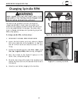
Страница 23: ...n the belt and serious personal injury will occur Figure 20 Spindle RPM chart at 60 Hz To change spindle RPM do these steps 1 DISCONNECT THE DRILL PRESS FROM POWER 2 Loosen the belt tension lock knob...

Страница 24: ...he drill bit to the required height 2 Thread the depth nut down against the stop bracket 3 Lower the jam nut against the depth nut 4 Hold the depth nut in place and tighten the jam nut against the dep...

Страница 25: ...23 M1102 M1103 16 Speed Drill Press OPERATIONS...

Страница 26: ...24 M1102 M1103 16 Speed Drill Press OPERATIONS...

Страница 27: ...FROM POWER 2 Rotate the downfeed handles until the drift key slot is exposed in the side of the quill For now keep the downfeed handles in this position 3 Move the table up until it is 1 4 below the...

Страница 28: ...n Too much lubrication will attract dirt and sawdust and various parts of your machine could loose freedom of move ment Periodic maintenance on your Model M1102 and M1103 Drill Press will ensure its o...

Страница 29: ...t spindle speed for task 2 Machine is undersized for the task 3 Bit or cutter is dull 4 Low power supply voltage 5 Belt s is slipping 6 Plug or receptacle is at fault 7 Motor connection is wired incor...

Страница 30: ...bearings at fault 1 Inspect replace for stripped or damaged bolts nuts and re tighten with thread locking fluid 2 Replace realign belts with a new matched set and retension belts refer to Page 21 3 Re...

Страница 31: ...the tapered chuck and spindle mating surfaces then reassem ble 2 Replace The spindle does not retract com pletely in the uppermost posi tion or it binds 1 The quill shaft is gummy with sawdust and oil...

Страница 32: ...ot from the locking lug Note It is important to keep a good grip during this step Letting go of the cover will cause the spring to rapidly uncoil 5 Rotate the cover counterclockwise to increase spring...

Страница 33: ...103 16 Speed Drill Press SERVICE Electrical Components Figure 30 Light socket with dust plug removed Light Switch Power Switch Figure 28 Power and light switch assembly Figure 29 Capacitor Light Socke...

Страница 34: ...32 M1102 M1103 16 Speed Drill Press SERVICE Wiring Diagram PARTS 110V Wiring Diagram M1102 M1103...

Страница 35: ...33 M1102 M1103 16 Speed Drill Press SERVICE Service Notes...

Страница 36: ...34 M1102 M1103 16 Speed Drill Press PARTS M1102 M1103 Parts Diagram...

Страница 37: ...NG AND CAP 50 XM1102050 POINTER 18 XM1102018 RUBBER BUSHING 51 XM1102051 TABLE SUPPORT ASSEMBLY 19 XM1102019 SWITCH BOX 52 XPB154M HEX BOLT M16 2 X 30 20 XPS09M PHLP HD SCR M5 8 X 10 53 XPLW10M LOCK W...

Страница 38: ...COVER 77 XPFS11M FLANGE SCREW M6 1 X 10 90 3 XPC150A CAPACITOR 150MFD 250VAC 78 XM1102078 BELT COVER KNOB M6 1 90 4 XPFB12M FLANGE BOLT M8 1 25 X 18 79 XPVM22 V BELT M 22 3L220 91 XPS09M PHLP HD SCR M...

Страница 39: ...ATA LABEL 197 XM1102197 BELT SPEEDS LABEL 95 97 Label Placement and Parts Safety labels warn about machine hazards and how to prevent machine damage or injury The owner of this machine MUST maintain t...

Страница 40: ...38 M1102 M1103 16 Speed Drill Press PARTS Parts Notes...

Страница 41: ...he defect resulted from causes not within the scope of Woodstock International Inc s warranty then the original owner must bear the cost of storing and returning the product This is Woodstock Internat...

Страница 42: ...ood value _____ Yes ____ No 5 Would you recommend Shop Fox products to a friend _____ Yes ____ No 6 What is your age group _____ 20 29 ____ 30 39 ____ 40 49 _____ 50 59 ____ 60 69 ____ 70 7 What is yo...

Страница 43: ...TAPE ALONG EDGES PLEASE DO NOT STAPLE FOLD ALONG DOTTED LINE FOLD ALONG DOTTED LINE WOODSTOCK INTERNATIONAL INC P O BOX 2309 BELLINGHAM WA 98227 2309 Place Stamp Here...

Страница 44: ......

Отзывы: