


1
BEFORE BEGINNING
Identify and verify that you have all the parts listed.
Read the instructions at least once, familiarizing yourself with
the parts, before beginning assembly. You’ll need two 7/16"
wrenches, a #3 Phillips screwdriver and a flat blade screwdriver.
ASSEMBLY
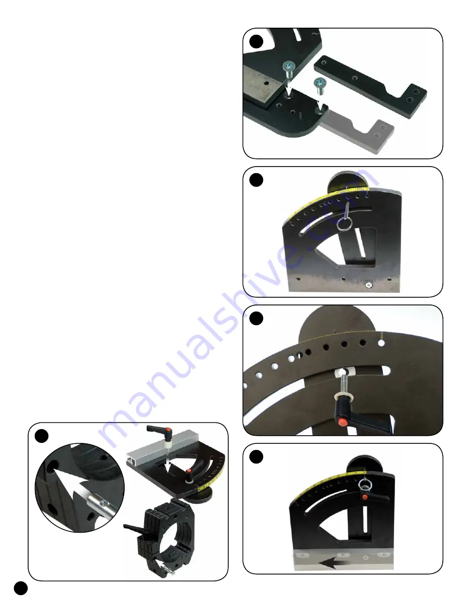
Find the side/arm assembly
(1470AS)
that has the
arm with the squared-off corner. Get the adjuster arm
(1475A1)
from the
1475 Height Adjuster
package and
attach it to the squared-off arm as shown, using two 3/4"
screws
(MF010)
. Pivot the arm as necessary to access the
lower mounting hole in the arm. Set the remaining height
adjuster parts and hardware aside until later.
See fig. 1.
Take both side/arm assemblies and align the pointer
in the arm with the 10º mark on the scale on the top of
the side.
Insert a pin
(Ringpin1)
through the 10º hole
in the side and into the hole in the arm.
See fig. 2.
Install a washer
(WB002)
and a nylon washer
(WN001)
on the stud of the knobs
(5863).
Slide another nylon washer
(WN001)
between the arm and side. A credit card can help
position the washer. The washer must be aligned with the
curved slot in the side and the threaded hole in the arm.
Insert the stud of the knob thru the curved slot in the side,
screwing it into the arm, then tighten the knob.
See fig. 3.
Insert 1" screws
(MF015)
thru the three countersunk
holes in each side and start an oval nut
(5760B - flat
side first)
on each screw. Slide a 7.5" deluxe track
(1470C)
on to the oval nuts on each Side. Center the
deluxe track on the side, check the side for square on
a flat surface and tighten the screws.
See fig. 4.
Remove the pin from each arm, loosen the
handle and rotate the arm to the 0º mark on the side,
then reinstall the pin and tighten the knob.
ATTACH ROUTER BLOCK
Set the router block
on end with the clamping
knob in the router block
(1470B or 1472B)
facing the
bottom. Insert a barrel nut
(5791B)
in the hole in the
face of the router block near the end. Use a flat blade
screwdriver to align the threaded hole in the barrel nut
with the cross hole in the router block.
See fig. 5.
1
2
4
3
Pin removed
for clarity
5


