3
BEFORE BEGINNING
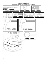
Identify and verify that you have all the parts listed. Read
the instructions at least once, familiarizing yourself with the
parts, before beginning assembly.
ASSEMBLY INSTRUCTIONS
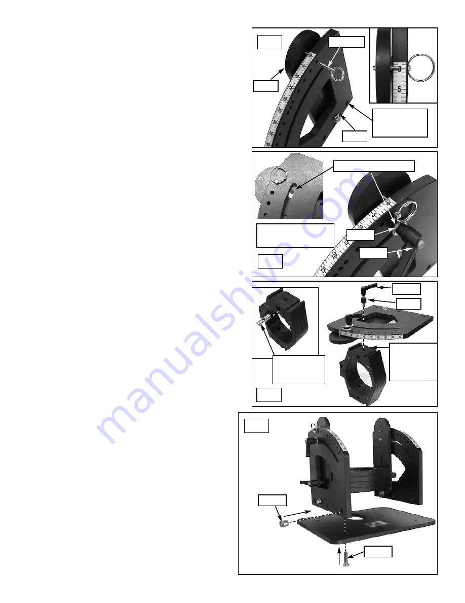
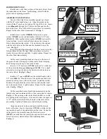
Set one of the Side/Arm assemblies upright on a bench
with the 45º scale mark facing you. Align the pointer in the
Arm with the 0º mark on the scale on the top of the Side. Insert
a pin
(Ringpin1)
through the 0º hole in the Side and into the
hole in the Arm. This will hold the Arm in place for assembly.
Repeat for the other Side/Arm assembly.
See fig. 1.
Install a brass washer
(WB002)
, followed by a nylon
washer
(WN002)
on the ratchet handles with the 1-1/8" stud
(5860-1.5).
Slide another nylon washer
(WN002)
between the
Arm and Side. A credit card will slip between the Arm and
Side to help position the washer. The washer must be aligned
with the curved slot in the Side and the threaded hole in the
Arm.
See fig. 2.
Insert the ratchet handle/washers thru the curved slot in the
Side and thread it into the Arm. Make sure there is a nylon
washer between the Arm and Side. Lightly tighten. Repeat for
the other Side/Arm assembly.
Set the router mounting block on a bench so that one of
the grooved ends is facing up with the router block clamping
knob facing away from you and to the bottom.
Insert a 1-1/8" barrel nut
(5791B)
into hole "A" in the face
of the router block
(see part drawing of 1425B)
. Use a small
screwdriver to align the hole in the barrel nut with the hole in
the router block.
See fig. 3, Step 1.
Install a 1/2" spacer
(PS001)
on the ratchet handle with 1-
5/8" stud
(5860-2).
Place the Arm of the right hand Side/Arm
assembly in the groove in the router block. Install the ratchet
handle with spacer thru the slot in the Arm and into the barrel
nut in the router block. Lightly tighten. Repeat for the opposite
side.
See fig. 3, Step 2.
Set the completed router block/side/arm assembly on the
labeled side (non countersunk side) of the router plate as shown.
See fig. 4.
The opening in the router block should be over the
bit opening in the router plate. It is critical to have the angle set
to "0º" and the router block fully lowered on the arms before
proceeding. Tighten all knobs securely before proceeding.
Align the six holes in the router plate with the slotted
holes in the sides. Insert a barrel nut
(5793B),
with the slot fac-
ing inward, in each of the slotted holes in the sides. Fasten the
router plate to the assembly using the flat head screws
(MF015)
, inserted thru the router plate and into the barrel nuts.
Get all six screws started before fully tightening them.
See fig. 4.
This is the right
hand Side/Arm
assembly
Step 1: 5791B
Barrel Nut
into hole "A"
Ringpin1
WN002 - Both locations
Attach ratchet handle
thru sides, into arms.
Fig. 1
Fig. 4
Fig. 3
Fig. 2
WB002
5860-2
5860-2
5793B
MF015
PS001
Arm
Side
Step 2: Arm
fits in groove
of the Router
Block


