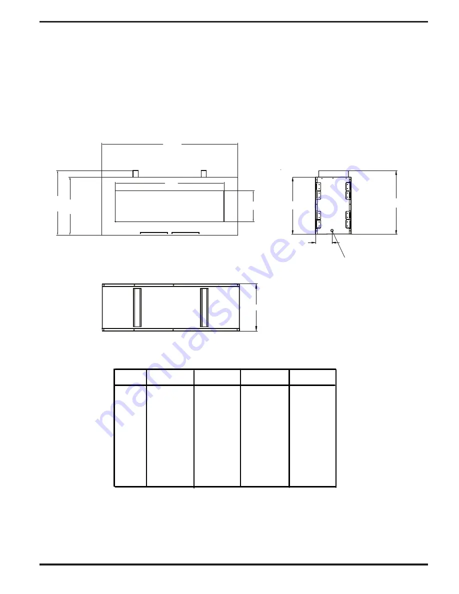
Woodbridge SS-36-N-ST Скачать руководство пользователя страница 5

5


FIREPLACE

 SPECIFICA


TIONS


DIMENSIONS

 48" 

 60" 

 72" 

 84" 

 29.75" 

 25.75" 

 25.75" 

 25.75" 

 36" 

 48" 

 60" 

 72" 

 17.31" 

 13.75" 

 13.75" 

 13.75" 

 33.75" 

 29.75" 

 31.75" 

 31.75" 

   RIGHT SIDE VIEW

8.15"

     FRONT VIEW

  TOP VIEW

GAS LINE ACCESS, BOTH SIDES

18"

 B

D

A

 C

 E


C

B

 SS-36-ST   SS-48-ST   SS-60-ST    SS-72-ST 

Содержание SS-36-N-ST

Страница 1: ...plliance 1 Do not store or use gasoline or other flammable vapors and liquids in the vicinity of this or any other aplliance Improper installation adjustment alteration service or maintenance can caus...

Страница 2: ...ng 14 Gas Connection 15 Checking Gas Pressure 16 Lighting Instructions 19 Operating Instructions 20 To Turn Off Gas to Appliance 21 Inspecting Burners 22 Cleaning and Maintenance 23 Troubleshooting 24...

Страница 3: ...Make certain you read and understand all warnings Keep this manual for reference It is your guide to safe and proper operation of this heater WARNING Any change to this heater or its controls can be...

Страница 4: ...f the control system and any gas control which has been under water 12 Turn replace off and let cool before servicing Only a quali ed service person should service and repair replace 13 Operating repl...

Страница 5: ...SIONS A 48 60 72 84 C 29 75 25 75 25 75 25 75 D 36 48 60 72 E 17 31 13 75 13 75 13 75 B 33 75 29 75 31 75 31 75 RIGHT SIDE VIEW 8 15 FRONT VIEW TOP VIEW GAS LINE ACCESS BOTH SIDES 18 B D A C E C B SS...

Страница 6: ...00 75 000 90 000 Shipping Weight Lbs 135 155 175 195 Gas Type Natural Natural Natural Natural S I T Control Valve Model 880 001 880 001 880 001 880 001 Ignition Electronic Electronic Electronic Electr...

Страница 7: ...T National Pipe Thread inlet connection to the pressure regulator WARNING Aquali edservice person must connect replace to gas supply Follow all local codes CAUTION Neverconnectpro pane LP replace dire...

Страница 8: ...nclosure in which the appliance is used shall comply with one of the following An enclosure with walls on all sides but at least one permanent opening at ground level and no overhead cover Within a pa...

Страница 9: ...NSTALLATION 9 Minimum 16 from both side walls 90 minimum ceiling height Standoff 0 0 mm IMPORTANT Floor must be non combustible Otherwise a minimum 1 thick cement board must be placed under the firepl...

Страница 10: ...N I N E T S A F COMBUSTIBLE MATERIAL NON COMBUSTIBLE MATERIAL AREA INSTALLATION Continued PLEASE NOTE Framing may need to be recessed from 3 4 to 1 1 2 depending on layers and type of facing material...

Страница 11: ...AIR VENT LEAVE MINIMUM 1 2 X 26 SLOT CLEAR FOR THE LOUVER AREA ON BOTH FACES Figure 1 1 Installation of facing materials Case 1 11 NON COMBUSTIBLE MATERIAL minimum INSTALLATION Continued F wide x H hi...

Страница 12: ...COVER WITH SECOND LAYER OF FACE MATERIAL SECOND LAYER LEAVE THE LOUVER AREA CLEAR WITH FIRST LAYER OF FACE MATERIAL FIRST LAYER Figure 1 2 Installation of facing materials Case 2 12 INSTALLATION Conti...

Страница 13: ...allow for minimum 13 sq inches Leave the louver area clear allow for minimum 13 sq inches INSTALLATION Continued OPTION 3 FACING WITH THICK LAYER OF NON COMBUSTIBLE ALLOWING AIR FLOW FROM BEHIND SURRO...

Страница 14: ...rdance with local codes or in the absence of local codes with the National Electrical Code ANSI NFPA 70 latest edition and Canadian Electrical Code CSA C22 1 INSTALLATION Continued IMPORTANT Floor mus...

Страница 15: ...ipe Tee Nipple Joint Natural Gas From Gas Meter 5 W C to 10 5 W C Pressure Propane LP From External Regulator 11 W C to 14 W C Pressure CAUTION Use only new black iron or steel pipe Inter nally tinned...

Страница 16: ...he appliance s rating decal If the gas supply is different from the fireplace STOP Do not install the appliance Contact your dealer immediately 2 To ease installation a 30 mm flex line with manual shu...

Страница 17: ...g show a leak 5 Correct all leaks at once 6 Reconnect replace and equipment shutoff valve to gas supply Check reconnected ttings for leaks INSTALLATION Continued Open Closed Equipment Shutoff Valve 2...

Страница 18: ...place media on burner or block air flow between burner and tray Your fireplace is ready for operation 18 glass media Verify burner and remote control operation NOTE Never operate the fireplace withou...

Страница 19: ...est for leaks DO NOT spray solution onto electronic parts DANGER Never use an open flame to check for gas leak WARNING If you do not follow these instructions exactly a fire or explosion may result ca...

Страница 20: ...l have a slight curve but ame should be blue and have no yellow or orange color If pilot ame pattern is incorrect Figure 7 Correct Pilot Flame Pattern Figure 7 shows a correct pilot ame Figure 8 shows...

Страница 21: ...ompressed air in a can You can use a vacuum cleaner in the blow position If using com pressed air in a can please follow the directions on the can If you don t follow directions on the can you could d...

Страница 22: ...ssembly 6 Replace pilot assembly gas company Cleaning and Maintenance 5 Replace gas control 1 Reconnect ignitor cable 1 Gas supply turned off or equipment shutoff valve 1 Turn on gas supply or open eq...

Страница 23: ...remote position ter and receiver 2 Pilot flame not touching 2 A Contact local propane LP flame sensor which al gas company lows flame sensor to cool causing pilot flame to go B Clean pilot see out Th...

Страница 24: ...ir is removed from line Have Remote does not function 1 Remote receiver locked 1 See instructions supplied with eRemote Control 2 Air passageways on heater 2 Observe minimum installa blocked lion clea...

Страница 25: ...th combustion air and create odors These odors will disappear over time 25 service person Fireplace produces a clicking ticking noise just after burners are lit or shut off Fireplace produces unwanted...

Страница 26: ...Proflame Wiring Diagram 4 5 21 Supplied 6 Volt Battery Backup 18 16 17 13 15 This diagram shows replaceable SIT Proflame parts used in your fireplace please refer to pages 27 31 26...

Страница 27: ...ILLUSTRATED PARTS BREAKDOWN 2 8 9 5 4 3 3 17 17 7 12 13 6 16 11 10 1 21 27 19...

Страница 28: ...3 H200012 H200012 WIRE HARNESS 1 14 C100020 A C100020 A DUPLEX POWER OUTLET not shown 1 15 PCB PCB SKYTECH REMOTE CONTROL 1 16 PCB R PCB R SKYTECH REMOTE RECEIVER 1 17 H100140 H100140 7V AC DC POWER A...

Страница 29: ...1 13 H200012 H200012 WIRE HARNESS 1 14 C100020 A C100020 A DUPLEX POWER OUTLET not shown 1 15 PCB PCB SKYTECH REMOTE CONTROL 1 16 PCB R PCB R SKYTECH REMOTE RECEIVER 1 17 H100140 H100140 7V AC DC POWE...

Страница 30: ...H200012 H200012 WIRE HARNESS 1 14 C100020 A C100020 A DUPLEX POWER OUTLET not shown 1 15 PCB PCB SKYTECH REMOTE CONTROL 1 16 PCB R PCB R SKYTECH REMOTE RECEIVER 1 17 H100140 H100140 7V AC DC POWER ADA...

Страница 31: ...0 C100080 1 2 X 48 FLEX CONNECTOR 2 11 D300090 D300090 SUPPLIED 1 2 SHUTOFF VALVE 1 13 H200012 H200012 WIRE HARNESS 1 14 C100020 A C100020 A DUPLEX POWER OUTLET not shown 1 15 PCB PCB SKYTECH REMOTE C...

Страница 32: ...erating instructions supplied with the appliance and does not extend to 1 firebox burner assembly damage by accident neglect misuse abuse alterations negligence of others including the installation th...

Отзывы: