10
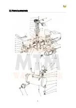
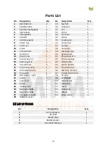
Parts List
No
Designation
Qty
1
Bolt M8x 110
4
29
Nut M8
2
Cylinder head
30
Capacitor
3
Cylinder head gasket
31
Fan
Valve plate
32
Circlip
5
Valve gasket
33
Fan cover
6
Cylinder
34
7
Cylinder gasket
35
Locating pin
8
Piston ring
36
Valve clack
9
Piston pin
37
Air filter
Piston
38
Connector
11
Screw M5x14
39
Discharge pipe
12
Handhold
40
Release pipe
13
Breath pipe
41
Pressure switch
14
Connecting rod
42
Pressure gauge
15
Rubber gasket
43
Outlet valve
16
44
Switch bracket
17
Crank case cover
45
Connector nut
18
Oil leveller washer
46
Dischang connect
19
Oil leveller
47
Unilateralism valve
20
Bolt M8x22 - right
48
Air tank
21
Crank
49
Bolt M8x25
22
Crank case
50
Washer foot
23
Motor
51
Washer 8
24
Sealing right
52
Nut 8
25
Bearing 6204RS
53
Drain cock
26
Bearing 6202RS
54
Wheel
27
Corrugated washer
55
Cover piece
28
Motor bracket
L
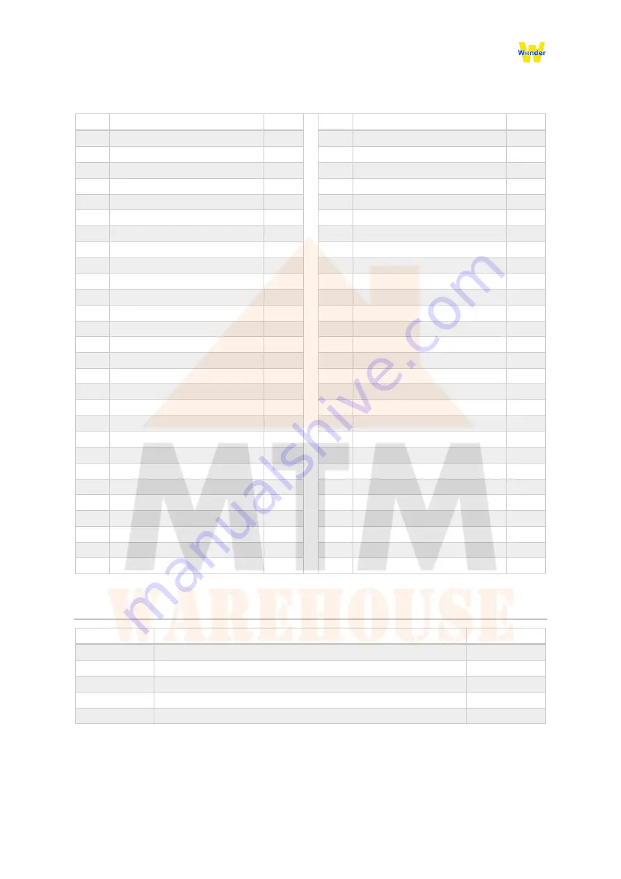
IST OF
G
OODS
No.
Air compressor
Air Filter
Breath Pipe
Rubber Gasket
Operation Manual
Страница 1: ...0 AIR COMPRESSOR OPERATION MANUAL PLEASE FAMILIARISE YOURSELF WITH THE OPERATION MANUAL FIRST BEFORE OPERATING THE AIR COMPRESSOR...
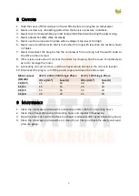
Страница 2: ...mpressor Head 3 Using the Sight Glass built into the lower front area of the Compressor just behind the Regulator check the oil level It should be at the halfway mark on the Sight Glass for normal ope...
Страница 3: ...Guidelines 3 Brief Description 4 General View and Main Components 5 Main Technical Parameters 6 Preparation for Starting 7 Operation and Adjustment 8 Cautions 9 Maintenance 10Troubles and Remedies 11...
Страница 4: ...in paint spray guns paint pumps etc and cause an explosion If you are using these solvents use only stainless steel spray equipment This does not affect your air compressor but many affect the equipm...
Страница 5: ...ng properly and to clear the valve of any possible obstructions 3 To provide proper ventilation for cooling the compressor must be kept a minimum of 31cm 12 inches from the nearest wall in a well vent...
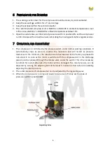
Страница 6: ...where compressed air is required 4 GENERAL VIEW AND MAIN COMPONENTS 1 Main Compressor 2 Pressure Switch 3 Outlet Valve 4 Regulating Valve 5 Pressure Gauge 6 Drain Cock 7 One way Valve 8 Wheel 9 Disch...
Страница 7: ...d by the pressure switch under normal working conditions It automatically stops as pressure reaches the maximum and will restart as pressure decreases to the minimum The rated pressure has been set at...
Страница 8: ...t work as the motor has stopped find the cause immediately so as not to damage the motor 9 Lubricating oil must be clean and the oil level should be kept in the red circle leveller 10 Disconnect the...
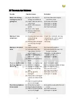
Страница 9: ...A foreign body may have gotten into the compressor 3 Piston knocking the valve seat 4 Moving parts seriously worn 1 Check and retighten 2 Check and clean away any foreign materials 3 Replace it with...
Страница 10: ...9 11 PARTS ILLUSTRATION...
Страница 11: ...re switch 1 14 Connecting rod 1 42 Pressure gauge 1 15 Rubber gasket 1 43 Outlet valve 2 16 Screw M5x14 6 44 Switch bracket 1 17 Crank case cover 1 45 Connector nut 1 18 Oil leveller washer 1 46 Disch...
Страница 12: ...11 Address 5 Lyn Parade PRESTONS NSW 2170 E mail sales mtmwarehouse com au Telephone 02 9607 4300...