background image


87 


domain should have the same Virtual ID.


Virtual IP


This is the virtual IP of the VRRP domain. This is the Gateway IP of the 

clients.


Priority 

The priority of the entry of this switch. In VRRP domain, the VRRP switches 

must have the same Virtual ID and Virtual IP settings and choose who 

should be the VRRP Master switch. The switch equips with the highest 

priority will be selected as the VRRP master. The priority setting field can be 

manually changed, the range is from 1~254, 255 for virtual IP owner and 

100 for backup by default. 

Adv. Interval 

This field indicates how often the VRRP switches exchange the VRRP 

settings. 

Preempt 

While the VRRP Master link is failure, the VRRP Backup will take over its job 

immediately. However, while the VRRP master link is recovered, who should 

be the Master? The Preempt decide whether the VRRP master should be 

recovered or not.   

While the Preempt is 

Enable 

and the interface is VRRP Master, the interface 

will be recovered. 

While the Preempt is 

Disable 

and the interface is VRRP Master, there is no 

change while the link is recovered. The VRRP backup acts as the Master 

before restart the switches. 

Click the 

Submit Selected 

button to apply the configuration. Click the 

Remove Selected 

button to remove selected 

setting. Click the 

Reload 

button to reload table. 


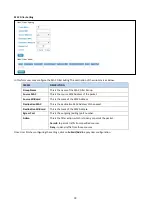
VRRP Status 

The VRRP represent for the Virtual Router Redundancy Protocol. To further ensure the high reliability of an 

environment, the Layer 3 switch supports the VRRP protocol allowing the hosts to continuously direct traffic to the 

default gateway without the default gateway configuration change. 


TERMS 

DESCRIPTION 

Interface


Select the interface for the VRRP domain.


VirtualID


This is a virtual ID range from 1~255. The switches within the same VRRP 

Содержание DP612

Страница 1: ...COVER DP612 Industrial 12G Layer 3 Managed PoE Switch DS612 Industrial 12G Layer 3 Managed Switch Jan 08 2018 V 1...

Страница 2: ...d does not claim to provide for every possible contingency met in the process of installation operation or maintenance Should further information be required or should particular problem arise which a...

Страница 3: ...TING 13 3 WEB MANAGEMENT CONFIGURATION 14 3 1 SYSTEM 16 3 1 1 INFORMATION 16 3 1 2 USER ACCOUNT 17 3 1 2 1 LOCAL USER 17 3 1 2 2 RADIUS SERVER 18 3 1 3 IP SETTING 19 3 1 3 1 IPv4 19 3 1 3 2 IPv6 20 3...

Страница 4: ...TUS 65 3 5 4 PVLAN SETTING 65 3 5 5 PVLAN PORT SETTING 66 3 5 6 PVLAN STATUS 67 3 5 7 GVRP SETTING 68 3 6 QUALITY OF SERVICE QOS 69 3 6 1 QoS SETTING 69 3 6 2 CoS MAPPING 70 3 6 3 DSCP MAPPING 71 3 7...

Страница 5: ...RT 104 3 12 DIAGNOSTICS 105 3 12 1 LLDP SETTING 105 3 12 2 MAC TABLE 106 3 12 3 PORT STATISTICS 108 3 12 4 PORT MIRROR 109 3 12 5 EVENT LOGS 110 3 12 6 PING 110 3 13 BACKUP AND RESTORE 111 3 14 FIRMWA...

Страница 6: ...c routing and VRRP guarantees sustainable routing in a single point of failure WoMaster managed switch is designed to provide faster secure and more stable network One advantage that makes it a powerf...

Страница 7: ...PS Dynamic Routing with Redundancy Protection RIPv1 v2 OSPFv1 v2 for intra domain routing within an autonomous system VRRP guarantees sustainable routing in a single point of failure Advanced manageme...

Страница 8: ...es hardware and contains information on installation and configuration procedures 2 1 HARDWARE DIMENSION Dimensions of DP612 85 5 x 150 x 126 5 W x H x D without DIN Rail Clip Dimensions of DS612 85 5...

Страница 9: ...onfiguration firmware management RJ 45 diagnostic console 1 x 8 pin terminal block connector 4 pin for power inputs 2 pin for digital input and 2 pin for alarm relay output and 1 chassis grounding scr...

Страница 10: ...l block connector 2 Tighten the wire clamp screws to prevent the power wires from being loosened 3 Connect the power wires to suitable AC DC Switching type power supply The input DC voltage should be...

Страница 11: ...s form a close circuit when a user configured event is triggered If a user configured event does not occur the fault circuit remains opened The fault conditions such as power failure Ethernet port lin...

Страница 12: ...r open trigger switch for control cabinet The switch s Digital Input accepts DC signal and can receive Digital High Level input DC 11V 30V and Digital Low Level input DC 0V 10V Here are the steps to w...

Страница 13: ...r better durability 2 6 DIN RAIL MOUNTING The EN50022 DIN Rail plate should already attached at the back panel of the switch screwed tightly If you need to reattach the DIN Rail attachment plate to th...

Страница 14: ...re and monitor the managed switch only For the CLI management interface please refers to the CLI Command User Manual PREPARATION FOR WEB INTERFACE MANAGEMENT WoMaster provides Web interface management...

Страница 15: ...management interface to introduce the featured functions User can use all of the standard web browser to configure and access the switch on the network Following topics are covered in this chapter 3 1...

Страница 16: ...cted to User network The figure below shows the interface of the Information section The description of the Information s interface is as below TERMS DESCRIPTION System Name Default switch Set up a na...

Страница 17: ...new password in this Local User section After finished click Submit to apply the changes Don t forget to Save the settings Try to re login with the new User Name and Password The description of the Lo...

Страница 18: ...IP Address b Enter the Shared Secret of the RADIUS server c Enter the Server port if necessary by default RADIUS server listens to port 1812 d Click Submit The description of the RADIUS Authenticatio...

Страница 19: ...as below TERMS DESCRIPTION DHCP Client Select to Enable or Disable to activate or deactivate the DHCP Client function IPv4 Configuration The IPv4 Configuration includes the switch s IP address and su...

Страница 20: ...fying the Prefix and using a EUI 64 interface ID in the low order 64 bits The host portion of the address is automatically generated using the modified EUI 64 form of the interface identifier Switch s...

Страница 21: ...ring node s IPv6 address Interface MAC Address and the current state of the entry The description of the columns is as below TERMS DESCRIPTION Neighbor Cache The system will update Neighbor Cache auto...

Страница 22: ...this box The system will send request packet to acquire current time from the NTP server that assigned Make sure that the switch also has the internet connection 1st Time Server 2nd Time Server Choos...

Страница 23: ...ents with prototype implementations of IEEE 1588 indicate that with suitable care the effect of these fluctuations can be successfully managed For example use of appropriate statistics in the 1588 dev...

Страница 24: ...the main option that needs to be enabled so that the PTP function will work Operation Mode Default Auto Elect Choose Mode Auto Elect Preferred Master Clock or Slave Synchronization Interval Default 0...

Страница 25: ...efault E2E Configures the delay mechanism in boundary clock mode E2E The delay request or response mechanism used in the boundary clock mode P2P The peer to peer mechanism used in the boundary clock m...

Страница 26: ...etwork Be sure to set user computers to be DHCP clients by setting their TCP IP settings to Obtain an IP Address Automatically When user turns the computers on they will automatically load the proper...

Страница 27: ...from the binding list select the index and click Remove To refresh the list click Reload Static MAC IP Binding List The figure below is the web interface for Static MAC IP Binding List Type the speci...

Страница 28: ...rule for a specific client The description of the columns is as below TERMS DESCRIPTION Circuit ID The Circuit ID of the device that wishes binding Remote ID The Remote ID of the device that wishes bi...

Страница 29: ...er LAN can be connected to the same port on the access switch and are uniquely identified The Option 82 information contains 2 sub options Circuit ID and Remote ID which define the relationship betwee...

Страница 30: ...the end device IP and the DHCP Option 82 server The Circuit ID is a 4 byte number generated by the Ethernet switch To activate this section please make sure that DHCP Relay Agent is enabled The format...

Страница 31: ...ow shows the DHCP Leased Entries It will show the MAC and IP address that was assigned by switch Click the Reload button to refresh the list The description of the columns is as below TERMS DESCRIPTIO...

Страница 32: ...Enable or disable a port Speed Duplex Default AutoNegotiation Users can set the bandwidth of each port as Auto negotiation 100 full 100 half 10 full 10 half mode for Giga Ethernet Port 1 8 ge1 ge8 Fo...

Страница 33: ...r Industrial Switch supports the SFP module with digital diagnostics monitoring DDM function User can check the physical or operational status of an SFP module via SFP DDM section This section shows a...

Страница 34: ...IEEE 802 3ad to bundle several physical ports together to form a single logical channel LACP mode is more flexible and it can change modes either trunk or single port Dynamic Port Trunk also provides...

Страница 35: ...s with 2 trunk members Since the member ports should use same speed duplex max trunk members would be 8 for 100Mbps and 2 members for Gigabit The description of the columns is as below TERMS DESCRIPTI...

Страница 36: ...distribution is based on the source and destination MAC address src ip load distribution is based on the source IP address dst ip load distribution is based on the destination IP address src dst ip lo...

Страница 37: ...ts When LACP links well User can see the member ports in aggregated column Individual Ports When LACP is enabled member ports of LACP group which are not connected to correct LACP member ports will be...

Страница 38: ...ype that wanted to filter Ingress The packet types of the Ingress Rule listed here include Broadcast Only Broadcast and multicast Broadcast Multicast and Unknown Unicast or All Egress The packet types...

Страница 39: ...ents traffic on a LAN from being disrupted by a broadcast DLF or multicast storm on a port In this page user can configure the storm control for each port Click Submit to apply the configuration TERMS...

Страница 40: ...rvice instance Continuity Check Protocol CCP Heartbeating messages for CFM The Continuity Check Message CCM provides a means to detect connectivity failures in an MA CCMs are multicast messages CCMs a...

Страница 41: ...the VLAN Please create VLAN first and each port set to be tagged Add the Domain association name end point type port number and and the MEP ID then click Add TERMS DESCRIPTION Domain Name Choose the...

Страница 42: ...d MEP ID Default 1 Choose the MEP ID One MEP refer to one MEP ID Domain Table This section shows the Domain entry User may delete the list by select the list and click Remove Selected Association Tabl...

Страница 43: ...standard and provides 240W power budget for hall system Power over Ethernet can be used with Surveillance cameras Security I O sensors Industrial wireless access points Emergency IP phones 3 3 1 PoE S...

Страница 44: ...the actual Voltage consumed value for PoE port Current mA Indicates the actual Current consumed value for PoE port 3 3 2 PoE CONTROL The PoE control includes 3 parts System Setting Port setting and P...

Страница 45: ...et control the PoE system will turn off low priority port PoE function until the consumption is becomes smaller than the system budget After finished configuring the settings click on Submit to save t...

Страница 46: ...upports hourly and weekly base PoE schedule configuration Enable and select the target port and marking the time frame then click Submit to activate the PoE scheduling function on selected port 3 3 4...

Страница 47: ...50 seconds Here we suggest that user sets the cycle time to 90 seconds Delete Delete PD s IP address that has been selected After finished configuring the settings click on Submit to save the configu...

Страница 48: ...ffic This is a particularly important feature for industrial applications since it could take several minutes to locate the disconnected or severed cable 3 4 1 RSTP SETTINGS This page allows select th...

Страница 49: ...ged to MSTP mode first After enabled MSTP mode user can go to the MSTP Settings page Bridge Configuration Bridge Address This shows the switch s MAC address Priority 0 61440 RSTP uses bridge ID to det...

Страница 50: ...y priority in a LAN Link Type There are 3 types for user selects Auto P2P and Share Some of the rapid state transitions that are possible within RSTP depend upon whether the port of concern can only b...

Страница 51: ...rwarding state in 4 seconds Once user finished user configuration click on Submit to save user settings RSTP Status This page allows user to see the information of the root switch and port status Root...

Страница 52: ...to apply user settings Add MSTP Instance This page allows mapping the VLAN to Instance and assign priority to the instance Before mapping VLAN to Instance user should create VLAN and assign the membe...

Страница 53: ...gned to interfaces that selected first and higher cost values that selected last If all interfaces have the same cost value the MSTP puts the interface with the lowest interface number in the forwardi...

Страница 54: ...user settings MSTP Status This page allows user to see the current MSTP status Choose the Instance ID first If the instance is not added the information remains blank The Root Information shows the se...

Страница 55: ...Ethernet ring loops can be avoided by guaranteeing that traffic may flow on all but one of the ring links at any time This particular link is called Ring Protection Link RPL A control message called R...

Страница 56: ...tance ID Select the Instance ID the available number is 1 15 VLAN Group Type the VLAN ID that user wants mapping to the instance Add ERPS Ring Add ERPS Ring is a section to add the Ring ID of the crea...

Страница 57: ...he Ring As interconnected sub ring will have only one ring port Port 1 is configured as 0 for interconnected sub ring 0 in this field indicates that no Port 1 is associated with this instance Choose t...

Страница 58: ...DESCRIPTION Ring ID Display the Ring ID Version ERPS Protocol Version v1 or v2 Ring State Default Disable Enabled Ring Status is enable Disabled Ring Status is disable Node State Status from the Ring...

Страница 59: ...TR Timer State Running or not Running status WTR Timer Period minute WTR timeout in milliseconds WTR Timer Remain ms Remaining WTR timeout in milliseconds WTB Timer State Running or not Running status...

Страница 60: ...ived R APS NR RB Tx The number of R APS messages with a No Request RPL Blocked NR RB being sent R APS NR RB Rx The number of R APS messages with a No Request RPL Blocked NR RB being received R APS NR...

Страница 61: ...nance VLAN the traffic must pass through a routing device or Layer 3 switch VLANs help control traffic VLANs increase the efficiency of User network because each VLAN can be set up to contain only tho...

Страница 62: ...ify different VLANs Valid VLAN ID is between 1 and 4094 Name A reference for network administrator to identify different VLANs The available character is 12 for User to input If User don t input VLAN...

Страница 63: ...s as below TERMS DESCRIPTION Not available U Untag Indicates that egress outgoing frames are not VLAN tagged T Tag Indicates that egress outgoing frames are to be VLAN tagged Steps to configure Egress...

Страница 64: ...ess port to segregate and preserve customer VLAN IDs for traffic crossing the service provider network 802 1Q Tunnel Uplink As the egress port that is the middle switch port Configures Q in Q tunnelin...

Страница 65: ...s this is a manually configured static VLAN This VLAN is not workable yet Dynamic means this VLAN is learnt by GVRP After created the VLAN the status of this VLAN will remain in unused status until Us...

Страница 66: ...ports it remains its original VLAN setting Host The Host type ports can be mapped to the Secondary VLAN Promiscuous The promiscuous port can be associated to the Primary VLAN VLAN ID After assigned th...

Страница 67: ...VLAN 2 Primary The member port of VLAN 2 is promiscuous port VLAN 3 Isolated The Host port can be mapped to VLAN 3 VLAN 4 Community The Host port can be mapped to VLAN 3 VLAN 5 Community The Host port...

Страница 68: ...e columns is as below TERMS DESCRIPTION GVRP Protocol Default Disable Allow user to enable disable GVRP function globally State Default Disable After enable GVRP globally here still can enable disable...

Страница 69: ...elies on a packet s CoS information to determine priority This is related to the settings in the CoS Queue Mapping page DSCP TOS Code Point If DSCP TOS is selected the switch relies on a packets diffe...

Страница 70: ...cal Queue mapping table WoMaster switch only supports 4 physical queues Lowest Low Middle and High represent by numbers from 0 to 3 In WoMaster switch users can freely assign the mapping table or foll...

Страница 71: ...CP value to the level of the physical queue Users can freely change the mapping table to follow the upper layer 3 switch or routers DSCP setting After configuration press Submit to enable the settings...

Страница 72: ...fundamental types of messages as shown below MESSAGE DESCRIPTION Query A message sent from the querier an IGMP router or a switch which asks for a response from each host that belongs to the multicast...

Страница 73: ...ll end stations on the LANs or VLANs that are connected to it For networks with more than one IGMP querier a switch with the lowest IP address becomes the IGMP querier TERMS DESCRIPTION Enable Default...

Страница 74: ...etting User can select Enable or Disable here After enabling IGMP Snooping User can then enable IGMP Snooping for specific VLAN User can enable IGMP Snooping for some VLANs so that some of the VLANs w...

Страница 75: ...tribute Registration Protocol GARP application that provides a constrained multicast flooding facility similar to IGMP snooping GMRP and GARP are industry standard protocols defined by the IEEE 802 1P...

Страница 76: ...IP destination due to the unique MAC address in the network It is so important to find out the destination MAC address so then the traffic can be correctly and smoothly directed to the destination An...

Страница 77: ...ERMS DESCRIPTION Interface The name of the IP interface Status After enabled the routing state the Status shows Up After disabled the routing state the status shows Down State Enable or Disable the IP...

Страница 78: ...route While configuring Default Route the IP address of the next hop router switch is the only setting needs to be specified Static Route Entry Static route entries go to and go from a stub network to...

Страница 79: ...ion Route Table Once the routing interfaces changed the system maintains information and updates the routing table It is important to find out the possible and best route in the field especially when...

Страница 80: ...d the update provides a smaller metric the existing entry in the local routing table is replaced Adds 1 or sometimes more if the corresponding link is slow to the metric If no route updated within the...

Страница 81: ...TERMS DESCRIPTION Interface The IP interface RIP Version RIP version of IP interface RIPv1 RIPv2 and Both Click the Submit button to apply RIP interface settings Click the Reload button to reload RIP...

Страница 82: ...group of routers the OSPF uses flooding to exchange link state updates between routers The routers within the same area update its routing table Any change in routing information is flooded to all rou...

Страница 83: ...ntified depends on what the bandwidth is by the system The value can be changed to decide the best router Priority The priority of this link Interface Set priority to help find the OSPF designated rou...

Страница 84: ...Areas are logical grouping of hosts and networks including their routers having interfaces connected to any of the included networks Each area maintains its own link state database In OSPF all areas...

Страница 85: ...rations OSPF Neighbor Table This page allows user to see the OSPF Neighbor information The Neighbor interface and its state will be listed here The Hello packets are exchanged between the switch to ne...

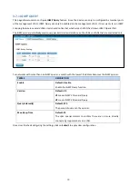
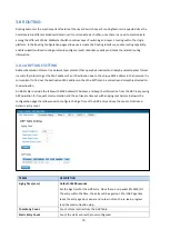
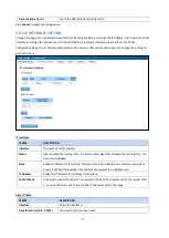
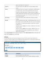
Страница 86: ...not stop VRRP Setting The fields allow you to create the Virtual Router Interface All the layer 3 switches within the same VRRP domain should be located within the same IP network and equips with the...

Страница 87: ...should be the Master The Preempt decide whether the VRRP master should be recovered or not While the Preempt is Enable and the interface is VRRP Master the interface will be recovered While the Preemp...

Страница 88: ...the VRRP Master switch The switch equips with the highest priority will be selected as the VRRP master The priority setting field can be manually changed the range is from 1 254 255 for virtual IP ow...

Страница 89: ...unity string set and remove the unwanted community string The community string can be viewed as the password because SNMP V1 V2c doesn t request User to enter password before User tries to access SNMP...

Страница 90: ...Hash Algorithm hash functions refer to five Federal Information Processing Standard approved algorithms for computing a condensed digital representation Authentication Password Here the user enters th...

Страница 91: ...P Trap Server IP Enter the IP address of the trap manager Community Enter the community string for the trap station Version Select the SNMP trap version type v1 or v2c After configuration Click Add th...

Страница 92: ...lists MAC Filter Network security can be increased by limiting access on a specific port only to users with specific MAC addresses Mac Filter feature allows User to stop the MAC address learning for s...

Страница 93: ...his is the mask of the MAC Address Destination MAC This is the destination MAC Address of the packet Destination Wildcard This is the mask of the MAC Address Egress Port This is the outgoing exiting p...

Страница 94: ...List 100 199 IP Extended Access List 1300 1999 IP Standard Access List expanded range 2000 2699 IP Extended Access List expanded range After entering the IP Filter Group number click the Add to create...

Страница 95: ...y traffic from those sources IP Filter List TERMS DESCRIPTION Select Selected the entry for delete Group Number Number of the Filter Group Type This is the filter group type standard or extended Proto...

Страница 96: ...to remove an attached MAC address filter IP Filter Select an IP address based filter to attach to the interface Select to remove an attached IP address filter Click the Apply button to apply the conf...

Страница 97: ...authorized users is maintained on a RADIUS server There is an authenticator our switch enabling 802 1X to forward the authentication requests between authentication RADIUS server and client Allowing...

Страница 98: ...gout Secondary Radius Server IP Secondary Radius Server could be set in case of the primary radius server down 802 1X Local User Here User can add Account Password for local authentication 802 1X Loca...

Страница 99: ...device connected to this port set the Host Mode to single means only the first PC authenticate success can access this port If this port is set to multi all the devices can access this port once any o...

Страница 100: ...st re authentication Click Default Selected to reset the configurable 802 1X parameters of selected port to the default values 802 1X Port Status User can observe the port status for Port control Auth...

Страница 101: ...owing table TERMS CONDITION DESCRIPTION Power Failure Power ID 1 Power ID 2 Any Detect power input status If one of condition occurred relay triggered Link Failure Port number Monitoring port link dow...

Страница 102: ...of event and setting the detail information and then clicks Submit to activate the relay alarm function 3 11 2 EVENT TYPE Event Types can be divided into two basic groups System Event and Port Event...

Страница 103: ...down Both The link status changed 3 11 3 SYSLOG SETTING System Log is useful to provide system administrator locally or remotely monitor switch events history There are 3 System Log modes provided by...

Страница 104: ...e email Server Mail Account Enter the email Server address Authentication Click on check box to enable password User Name Enter email Account name Max 40 characters Password Enter the password of the...

Страница 105: ...ter managed switch to periodically send its system and configuration information to its neighbors Because of this all LLDP devices are kept informed of each other s status and configuration and with S...

Страница 106: ...ss monitor the MAC address or sort them by different packet types and ports Click on Submit to change the value Aging Time Sec Each switch Fabric has limit size to write the learnt MAC address To save...

Страница 107: ...The address type description is below Static Unicast MAC address can be added and deleted Dynamic Unicast MAC is MAC address learnt by the switch Static Multicast can be added by CLI and can be delete...

Страница 108: ...kets If the table shows many Bad Abort or Collision counts increased that may mean network cable is not connected well the network performance of the port is poor etc Please check network cable Networ...

Страница 109: ...guration and settings explain as following TERMS DESCRIPTION Port Mirror Select Enable Disable to enable disable Port Mirror Source Port This is also known as Monitor Port These are the ports User wan...

Страница 110: ...Event index assigned to identify the event sequence Date The date is updated based on how the current date is set in the Basic Setting page Time The time is updated based on how the current time is se...

Страница 111: ...h CLI and Web UI The description of the columns is as below TERMS DESCRIPTION TFTP Server IP User needs to key in the IP address of TFTP Server here File Name Type the correct file name of the configu...

Страница 112: ...d TFTP Server mode In this mode the switch acts as the TFTP client Before do so make sure that TFTP server is ready Then please type the IP address of TFTP Server and Backup configuration file name Th...

Страница 113: ...function provides users with a quick way of restoring the WoMaster switch s configuration to factory defaults The function is available in the serial Telnet and web consoles Factory Default main scree...

Страница 114: ...ion will be logged out The Logout command allows user to manually logout the web connection Click on Yes to logout 3 18 REBOOT System Reboot allows user to reboot the device Some of the feature change...

Страница 115: ...ystem ready System not ready Ring Green on Ring is active Amber on Ring status is abnormal Ring is inactive DO Red on alarm relay active and contacts is short Red off relay output contact is open DI G...

Страница 116: ...nk Green On Active Green Blinking Speed 1000M Amber On Speed 100M Off Reset System Reboot 2 6 Seconds Default Settings Reset over 7 seconds System Reboot 2 6 Seconds Default Settings Reset over 7 seco...

Страница 117: ...gest to reserve 15 tolerance Max 16 08W 24VDC full traffic suggest to reserve 15 tolerance PoE PoE Model Only Power Forwarding Mode Alternative A PoE Power Budget System Max 240W 75 C Per Port Max 30W...

Отзывы: