background image

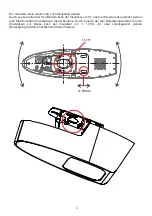
1. Connect power cord to the unit 

(#13)

 and to mains.

(all cables can be hidden by pulling them through the ceiling mount).

2. Connect a monitor or video projector to the HDMI output 

To select the proper output mode, please read the user manual!

3. Turn the main switch on the unit 

(#12)

 to “I” (Power LED must illuminate)

4. By default, the Visualizer will be fully powered-up when mains is supplied.

When the default behavior is changed by the user, press the POWER key

 (#29) 

on the remote control.

Preparation

Center the adjustment chart to the pick-up area and follow the further instructions on-screen.
Once the settings are correct, confirm it to complete the Height Adjustment Function. If the settings are 
incorrect, re-do the Height Adjustment or perform manual adjustment.

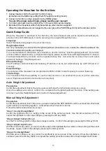
Operating the Visualizer for the first time

Auto Height Adjustment

10

When the Visualizer is switched on the first time, the Quick Setup Guide will be started automatically on-
screen (visible on HDMI output). Use the arrow keys to navigate through the menu. 

Language

Select the desired language for the on-screen menu.

Height Adjustment

.

For usual installations, WolfVision recommends to use the function “Auto Height Adjustment”. Should the 
unit be unable to adjust itself (e.g. bright ambient light), please use the “Manual Height Adjustment” instead.
The Height Adjustment procedure can be repeated at any time. Just enter the on-screen menu and select 
Advanced Settings / Height Adjustment.

Ethernet Settings

The IP-address, Subnet Mask and Gateway IP-address can be set automatically by a DHCP-server or 
manually.

Power Settings

The cameras of the Visualizer can be optimized to 50Hz or 60Hz mains frequency to reduce flickering.

Time Settings

The Visualizer offers the possibility to use the internal clock or an external time server (a time valid time 
server IP address and internet connection are required).

It is only necessary to conduct the Height Adjustment procedure once, unless the distance between the 
Visualizer and working surface is changed

Preparation

Center the adjustment chart to the pick-up area and adjust the VERGENCE until the vertical lines of left and 
right channel are matching together - vertical lines should result in one line.
Follow the further instructions on-screen.

Step 1: Center the Lightfield

Center the lightfield until it is roughly in the center of the camera picture. Use the arrow buttons

 (#17)

 to 

center the lightfield. Confirm the setting by pressing the OK key

 (#28)

.

Step 2: Adjust Camera Focus

” 

Use the FOCUS keys

(#22) 

until a sharp image is visible.  Confirm the setting by pressing the OK key 

(#28)

.

Step 3: Adjust Light Focus

” 

With the FOCUS key 

(#22), 

you can focus the edge of the lightfield that is visible on the working surface until 

it is sharp.  Again, confirm the setting by pressing the OK key 

(#28)

.    

Step 4: Center lightfield

With the arrow buttons you can center the lightfield to pick-up area of the camera. When the lightfield is 
centered, press the OK key 

(#28)

 to complete the setting procedure and exit the Height Adjustment mode.

Manual Height Adjustment

Quick Setup Guide

Содержание VZ-C3D

Страница 1: ...Check out our Internet Homepage for additional information www wolfvision com support INSTALLATION MANUAL MONTAGEANLEITUNG INSTALLATION MANUAL MONTAGEANLEITUNG ENGLISH DEUTSCH VZ C3D VZ C3D R...

Страница 2: ...firmly in place Do not expose the unit to water metallic objects or any flammable material Avoid installing the unit in locations exposed to strong magnetic fields or electrical currents Avoid instal...

Страница 3: ...ording to Directive EMC and to Directive electrical equipment Inspections tests and evaluation are according to UL60950 CSA22 22 60950 Inspections tests and evaluation are according to the CB Scheme I...

Страница 4: ...ansport damage In the event that damage is found call your WolfVision dealer immediately and do not attempt installation of the Ceiling Visualizer 2 Confirm that all parts and are present accessories...

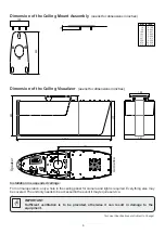
Страница 5: ...1 50m 1 60m 1 70m 1 80m 2 00m 39 37 7 24 55 12 62 99 70 87 78 74 86 61 4 0 00 3 94 7 87 11 81 15 75 19 69 23 62 27 56 31 50 35 43 39 37 43 31 47 24 51 18 55 12 59 06 62 99 66 93 70 87 78 74 Object di...

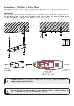
Страница 6: ...vented Important Please give special attention to the country specific regulations for training and conferencing rooms G IMPORTANT Ensure solid mounting and secure connection of all parts to avoid the...

Страница 7: ...eiling Visualizer see list for dimensions in inches IMPORTANT Sufficient ventilation is to be provided otherwise it can result in damage to the equipment G Installation in suspended ceilings For norma...

Страница 8: ...t of 26kg 58lbs and that possible collision accidents are prevented direction of speaker Final position of the Visualizer with ceiling mount Inch mm 8 0 315 15 0 59 17 0 67 61 2 4 IMPORTANT Please giv...

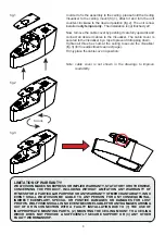
Страница 9: ...G WHICH DOES NOT PROVIDE A SUFFICIENTLY SECURE SUPPORT OR 3 ANY OTHER FAULTY WORKMANSHIP 8 In order to fix the assembly to the ceiling please hold the Ceiling Visualizer to the ceiling mount fig 1 att...

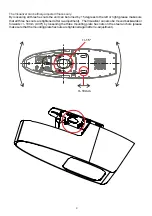
Страница 10: ...the left or right please make sure that all three hex nuts are tightened after re adjustment The Visualizer can also be moved backwards or forwards 10mm 0 39 by loosening the three mounting plate hex...

Страница 11: ...htAdjustment Ethernet Settings The IP address Subnet Mask and Gateway IP address can be set automatically by a DHCP server or manually Power Settings The cameras of the Visualizer can be optimized to...

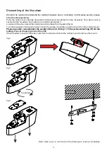
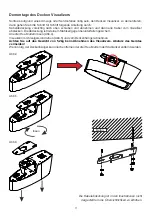
Страница 12: ...from the Visualizer The cable cover is secured to the Visualizer by a rope to prevent it dropping down Loosen all three hex nuts at the ceiling mount to release the Visualizer fig 4 Turn the Visualiz...

Страница 13: ...S GER T VOR HITZE UND FEUCHTIGKEIT SCH TZEN DAS GER T VOR ERSCH TTERUNG SCH TZEN Bitte darauf achten dass eine ausreichende Luftzirkulation zur K hlung des Ger tes m glich ist L ftungsschlitze oben un...

Страница 14: ...hgef hrt Pr fungen Tests und Untersuchungen wurden nach dem PCT Schema durchgef hrt Aufkleber am Ger t Pr fungen Weltweite Patente Copyright Information EU 0 362 737 KR 128059 AU 765617 DE P58907684 1...

Страница 15: ...ungen d rfen nicht au er Betrieb gesetzt oder entfernt werden G Lesen Sie die Installationshinweise durch bevor Sie mit der Installation beginnen Aufgrund der breiten Palette von Installationsm glichk...

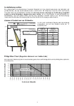
Страница 16: ...hang zwischen der Montageh he und der Bildgr e optischer Zoombereich Bildgr en Chart Regul rer Abstand von m 1m bis 2 2 0 00m 0 10m 0 20m 0 30m 0 40m 0 50m 0 60m 0 70m 0 80m 0 90m 1 00m 1 10m 1 20m 1...

Страница 17: ...ision auszuschlie en Au erdem sind die l nderspezifischen Bestimmungen f r Schulungs und Konferenzr ume zu beachten Installation mit einem zus tzlichen Deckenh nger Fremdhersteller Beim Einbau in eine...

Страница 18: ...orbehalten WICHTIG F r eine ausreichende Bel ftung ist zu sorgen andernfalls kann es zu einer Besch di gung des Ger tes kommen G Einbau in abgeh ngte Decken F r den normalen Betrieb ist nur eine Ausne...

Страница 19: ...er montiert werden soll muss in jedem Fall f r eine Tragf higkeit von 26kg ausgelegt sein um m gliches Herunterst rzen durch Kollision auszuschlie en WICHTIG Richtung Anwender Decken Visualizer mit De...

Страница 20: ...zu erh hen Nun die Kabelabdeckung durch vorsichtiges nach oben Schieben entfernen und dann alle gew nschten Kabel anschlie en Die Kabelabdeckung ist mit einem Stahlseil gegen herunterfallen gesichert...

Страница 21: ...ann der Visualizer um 15 nach rechts oder links gedreht werden alle Klemmmuttern anschlie end wieder fixieren Durch Lockern der drei Befestigungsmuttern an den Stahlankern zur Decke kann der Visualize...

Страница 22: ...Die IP Adresse Subnetzmaske und die Gateway IP Adresse kann von einem DHCP Server automatisch bezogen oder manuell gesetzt werden Einschaltverhalten Die Kameras des Visualizers k nnen auf die Netzfre...

Страница 23: ...en DieAbdeckung ist mit einem Stahlseil gegen herunterfallen gesichert Alle drei Hex Muttern l sen Abb 4 Visualizer im Uhrzeigersinn drehen Abb 5 und vom Deckenh nger abnehmen Wenn n tig der Deckenh n...

Страница 24: ...okyo Tel 81 0 3 3360 3231 Fax 81 0 3 3360 3236 E mail wolfvision japan wolfvision com Canada WolfVision Canada Inc Ottawa Tel 1 613 741 9898 Toll free 877 513 2002 Fax 1 613 741 3747 E Mail wolfvision...

Отзывы: