
5
Installation instructions Remote 3000 / 3010
5 Technical data
Technical data
Dimensions lock (mm)
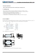
BxHxT, see fig. 1 page 2
Material
zinc plated steel sheet
Ingress protection
IP30
Temperature (°C)
5-40
Rel. humidity (%)
10-75 % not condensating
Operation conditions
(standby *1)
supply voltage 12VDC, only power supply without any
control contacts
(load *2)
7.5 N bold force, supply voltage 12VDC
(bold blocked *3)
supply voltage 12VDC
Power supply
Voltage
(Vcc)
9-12 VDC +/- 10%
Current consumption
(standby *1)
(load *2)
(max. *3)
typ. 1 µA
< 300 mA
< 700 mA
Current consumption control inputs
- Open/close (mA)
- Blocking (mA)
< 0.5 mA
< 0.1 mA
Voltage levels control inputs
- Open/close
- Blocking
(always with reference to ground)
5V – 12 V (max. Vcc)
0-5 V
Output
- „Secured“
5-500mA@30V
(data sheet Cherry DH)
Terminal block wire gauge
0.13 – 0.5 mm² respectively AWG 26-20
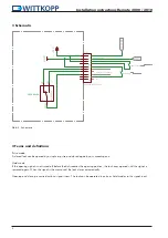
• The blocking input allows to inhibit lock openings. Closing or accordingly extending the bolt, is still possible.
• The lock electronically checks at the beginning of every opening cycle, whether a blocking signal is active. To combine multi-
ple locks like a double door system, only one common signal line is necessary (easier cabling).
• The condition „secure“, when the bolt is in closed position and retained, is signalized by switching contacts directly connected
to the terminal block (dry-contact).
6 Functional test
(when the door is open)
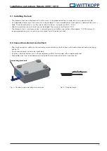
• Carry out a functional test after installing the lock.
• Trigger the control signal.
• The lock bolt moves in automatically (has to happen easily). The lock is opened.
• After triggering another control signal (pulse mode) or after switching off the control signal (hold mode) the lock bolt moves
out automatically and locks. The lock is closed.
• Keep enough clearance to the locking point.


