Project planning guide
cyber
®
reaction wheel 2
en-30
Doc. no.: 5022-D060586
Revision: 02
3.4 Prototypical integration of the cyber
®
reaction wheel 2 into an ADCS environment
For control and diagnosis of the reaction wheel with a microcontroller, e.g. an ADCS, the
interfaces I2C, SPI and UART as well as a Wittenstein communication stack are provided as
a C code. All relevant functions for control and diagnostics of the reaction wheel are
implemented in the stack provided. A documentation can be found in the download portal of the
cyber
®
reaction wheel 2 in the Interface Control Document (https://cyber-
motor.wittenstein.de/de-de/download-reactionwheel/).
Basic control of the drive system with a microcontroller platform is explained below.
3.4.1 Preparations at the cyber
®
reaction wheel starter kit
Communication with the cyber
®
reaction wheel 2 via the cyber
®
reaction wheel starter kit is
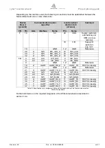
realized via application interface B with pin assignment according to table 11 in section
2.2.5.22.2. Depending on the required communication interface, the corresponding pins must be
connected to the pins of a suitable microcontroller.
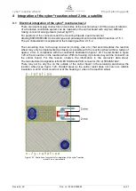
In addition, the logic voltage (3.3 V or 5 V) must either be supplied externally at pin 19,
connector B or a connection must be established to the internal 3.3 V or 5 V via a 0 Ω resistor
(see section 2.2.7.2).
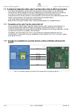
3.4.2 Example of an integration of a reaction wheel for startup via SPI with a Nucleo board
from ST
Figure 1.20: Schematic integration of the starter kit with reaction wheel for initial startup using SPI
SPI_nCS
µC PCB, e.g. Eval Board
for ADCS
SPI_MISO
SPI_MOSI
SPI_CLK
GND
V-IO
V-IO
Wittenstein
Stack
ADCS
software


