background image

8

WPS-550-DOM-A Installation Manual

INSTALLATION

1.  Prepare Camera for Mounting

Prior to mounting to the Camera, we recommend that the position 
and angles be preset in order to speed installation.  These settings 
can be fine-tuned once the Camera is mounted.

Important Note: To avoid damaging the dome surface during installation, keep the 

dome surface away from walls and other objects. Do not remove the protective 
coating from the dome until after the camera is mounted and the dome installed.

Microfiber or similar cloths can be abrasive, only use a dry eyeglasses cloth when 

cleaning he lens to avoid damage that can blur the cameras image.

1.  Connect The Camera to the System
Recommended Cabling
    Video 

RG59 or RG6

    Power 

18/2 or Cat5e/6

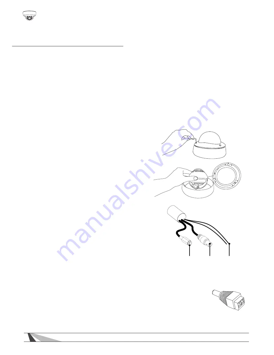
A.   Open the camera by using 

the provided 3mm Allen key to 
remove the three screws on the 
dome cover.

B.   Pre-adjust the camera’s 3-axis 

angle so the lens points in the 
desired direction. The lens angle 
should not exceed 50˚ off the 
center axis.

A.  Connect the BNC video output to the 

video in of a DVR or monitor.

B.  Connect the DC Power In to a power 

supply using the included WPS-ACC-PWR DC power adapter. The power 
supply can be located at the head end of system using a WPS-PS 
multiple output power supply and prewiring a power wire.

C.  The RS485 leads to a WPS-CCTV-TESTER, DVR, or PTZ controller to 

view, and control the OSD menu.

Important Note! Be sure to use the correct power supply and power wire for the length 
of run to the camera to ensure reliable operation. Too small a power supply or wire will 
cause too much voltage drop, which will cause the camera to operate incorrectly or not 
power up at all.

12V DC

Power In

BNC

Video Out

RS485 Leads

Содержание WPS-550-DOM-A-BL

Страница 1: ...WPS 550 DOM A BL WPS 550 DOM A WH CAMERA DOME INSTALLATION MANUAL Review manual thoroughly before installation Retain for future reference...

Страница 2: ...Set Up 8 1 Operating The OSD Menu 11 2 OSD Menu Structure 11 3 OSD Menu Settings 15 3 1 Lens 15 3 2 Exposure 15 3 3 White Balance 16 3 4 Backlight 17 3 5 Day Night 18 3 6 DPC 19 3 7 Special 19 3 8 Co...

Страница 3: ...ra only operates under temperature conditions between 14 F 140 F 3 Do not mount the camera directly facing bright light sources Exposing the camera to strong light over long periods of time will damag...

Страница 4: ...producing a more balanced image 2D Digital Noise Reduction Digital noise reduction produces clear images in low light conditions Not only does it help to reduce image noise but it also minimizes objec...

Страница 5: ...ers a wide range of accessories that provide power to the cameras allow for various mounting options and make connection to the head end quick and easy WPS MNT EXT DOM Dome Camera Extension Mount Use...

Страница 6: ...Remote Power Supplies Use these remote power supplies to power all the cameras in the system from a remote location WPS PS9 12VDC 10A 9 Output Power Supply 12V DC 10A PTC Fuses WPS PS9 24VAC 12A 9 Ou...

Страница 7: ...nd Screw Terminals WPS BAL V COMBO Mini Passive Video Balun with Screw Terminals Combo PackContains 1 WPS BAL V PIGTAIL and 1 WPS BAL V MINI WPS BAL VP Passive Video and Power Balun with RJ45 WPS BAL...

Страница 8: ...pen the camera by using the provided 3mm Allen key to remove the three screws on the dome cover B Pre adjust the camera s 3 axis angle so the lens points in the desired direction The lens angle should...

Страница 9: ...ll or eve A 1 Use the provided foam gasket as a template to pre mark mounting hole locations A 2 Predrill holes in the marked locations A 3 Connect the wires from the wall to the Cameras Pigtail and i...

Страница 10: ...The Test Port adapter power connection for this camera only uses a 12 V DC power supply Using a 24 V AC or other voltage power supply with the Test Port Adapter will result in damage to the camera and...

Страница 11: ...SD MENU page Press UP DOWN EXIT Left or ENTER Right to select items on the menu and begin configuration OSD Menu Structure Settings have been preconfigured for optimal performance in most applications...

Страница 12: ...EL N D DELAY RETURN BURST IR SMART IR LEVEL RETURN ON OFF ON OFF LOW HIGH 100 1 SEC 35 5 SEC BACKLIGHT BLC HLC OFF AREA SEL AREA STATE GAIN HEIGHT WIDTH LEFT RIGHT TOP BOTTOM RETURN LEVEL MODE RETURN...

Страница 13: ...FONT COLOR CONTRAST SHARPNESS ON OFF ON OFF ON OFF AREA SEL AREA STATE HEIGHT WIDTH LEFT RIGHT TOP BOTTOM DEGREE VIEW RETURN AREA SEL AREA STATE HEIGHT WIDTH LEFT RIGHT TOP BOTTOM COLOR RETURN ON OFF...

Страница 14: ...ACTORY RETURN DISPLAY NEG IMAGE CAM ID ID DISPLAY BAUD RATE PROTOCOL ID POS RETURN ENGLISH RESET CRT LCD USER ON OFF 1 255 1 ON OFF 2400 4800 9600 19200 38400 57600 PELCO D PELCO P PED LEVEL COLOR GAI...

Страница 15: ...ded for an environment with consistent lighting conditions EXPOSURE SHUTTER Setup Shutter setup allows for control of the electronic shutter speed Select a shutter speed to match the lighting conditio...

Страница 16: ...amic Range SETUP DWDR improves the contrast between very dark and very bright areas in a scene and producing a more balanced image Adjust the level from 1 to 63 based on the environment Choose OFF to...

Страница 17: ...e of BLUE and RED to a user preferred white balance image BACKLIGHT BLC Back light compensation Setting This function corrects the exposure of subjects or objects in front of a bright light source Cho...

Страница 18: ...cation AUTO The camera uses the lens to determine color or B W When in AUTO mode the camera automatically switches to B W when lighting levels are low and back to color when they increase COLOR The ca...

Страница 19: ...30 seconds B W Setting BURST ON The B W image is actually a grey image and contains the color signal OFF This is a true B W image containing no color signal IR SMART When an image is too close to the...

Страница 20: ...llows for monitoring motion more efficiently Set MOTION DET to ON to enter into the Motion subdirectory for settings Select zones 1 4 under AREA SEL to adjust the settings of the area zone for motion...

Страница 21: ...color include 16 different colors for each privacy zone Change the color by selecting a value from 0 to 15 PARK LINE Setting The PARK LINE function may be useful if the camera is used in a mobile appl...

Страница 22: ...ange colors by selecting a value from 0 to 15 steps CONTRAST When increasing the contrast value dark colors become darker and light colors become lighter The value ranges from 0 to 255 SHARPNESS When...

Страница 23: ...used in the surveillance system confirm that no other device is using the same ID If two or more devices share the same ID number the PTZ controller or DVR will not be able to control or configure an...

Страница 24: ...selecting FACTORY RESET and pressing the MENU button This option does not have an UNDO feature so ensure default settings are desired before selecting this function EXIT RESET FACTORY RESET RETURN RET...

Страница 25: ...25 WPS 550 DOM A Installation Manual 2013 Wirepath Surveillance SYSTEM DIAGRAM RS485 Cable ID 2 ID 0 ID 1 DVR PTZ Controller ID 3 ID 4 ID 255...

Страница 26: ...Nothing appears on the display Check if the power for camera and monitor is ON Check if the VIDEO cable is connected to the camera BNC video output jack Check if the VIDEO cable is connected to the m...

Страница 27: ...settings AGC settings are not available DAY NIGHT Mode is set to AUTO To enable AGC control change DAY NIGHT to EXT Color or B W RS 485 communication failure Check whether the RS 485 polarity is conne...

Страница 28: ...ting on a metal box Condensation Appears on Camera Lens Cover Check the color of the beads in the Silica pack under the lens cover If the blue crystals have turned pink indicating that the pack has ab...

Страница 29: ...s Yes IR Range 65 ft Smart IR Yes True Day Night Yes Technology OSD Yes WDR D WDR DNR 2D DNR Minimum Illumination 0 01 Lux color 0 Lux IR on Highlight Compensation Yes Auto Gain Control Yes Back Light...

Страница 30: ...30 WPS 550 DOM A Installation Manual DIMENSIONS DIMENSIONS Top View Side View 5 91 4 04 67 0 67 0 Maximum Camera Angle...

Страница 31: ...components found to be defective in material or workmanship under normal conditions of use This warranty shall not apply to products which have been abused modified disassembled or improperly install...

Страница 32: ...130424 1545 2013 Wirepath Surveillance...

Отзывы: