background image

1126700

SmartPAC 2 User Manual

6-30

Run Mode

ERROR/EVENT LOG

(RUN – ERROR LOG)

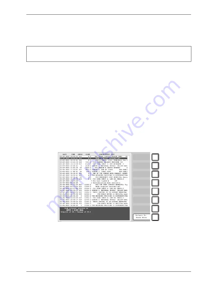
This item enables you to view a list, called the Error/Event Log (see Figure 6-24), tha
displays in reverse chronological order the 100 most recent errors or events that have occurred 
at the press or within SmartPAC 2.

The Error/Event Log is useful as a troubleshooting aid.  Each time the press is stopped due to 
a fault, the log records the error message, which gives the reason for the stop, and the stroke 
count and crankshaft angle at which the stop occurred.  When a new tool is loaded, the log 
displays the tool number.  If SmartPAC 2 is connected to a computer network and e-mail is 
enabled, the log also shows messages sent by SmartPAC 2.  When SmartPAC 2 is networked, 
you can send the Error/Event Log to Wintriss Tech. Support (see MESSAGING, page 6-32).  
Error messages displayed on the Error/Event Log are documented in Chapter 7.

To view the Error/Event Log, do the following:

1.

Select ERROR/EVENT LOG on the Main Run Menu to display the Error/Event Log.

2.

Use the cursor keys to scroll through the errors and events.  When an error is selected, the 
full text of the error message is displayed in the blue window at the bottom of the screen.

For HELP with the Error/Event Log, press the HELP key when the screen is displayed.


Figure 6-24. Error/Event Log

NOTICE

F1
F2
F3
F4
F5
F6
F7
F8

Содержание SmartPAC2

Страница 1: ... ProCam PAC 1126700 Rev F October 2014 User User User Manual Manual Manual User Manual Tech Support Hotline 800 586 8324 8 5 EST www wintriss com Wintriss Controls Group LLC 100 Discovery Way Unit 110 Acton MA 01720 USA Phone 800 586 8324 Fax 978 263 2048 PRINTED IN USA DA70070 ...

Страница 2: ... User Manual 1126700 This revision of the SmartPAC 2 user manual covers SmartPAC 2 software version 12 73 and higher The changes include Added to the cover of the installation manual the URL and QR code user needs to download the user manual ...

Страница 3: ...e returning We ask that you either fax us a PO for that amount or enclose the PO with the returned item This will enable us to ship the item back to you as soon as the repair has been completed If the item cannot be repaired or there are additional charges you will be contacted for approval Please be sure to carefully pack all returned items and ship to our Acton MA location Expedited Repair Progr...

Страница 4: ...ling SmartPAC 2 as a Panel Mount 2 8 Installing the Resolver 2 10 Mounting the Resolver 2 11 Wiring the Resolver 2 12 Connecting AC Wiring 2 14 Connecting Stop Circuits and Input Check Circuit 2 15 Making Wiring Connections 2 16 Setting the Input Check Voltage Switch 2 16 Connecting to Network 2 17 Adding or Upgrading DiProPAC or ProCamPAC 2 18 Replacing an Existing Board 2 18 Installing a New Boa...

Страница 5: ... 43 Wiring Tables for SmartPAC 2 Options 2 43 Chapter 3 SmartPAC 2 Keyboard Displays and Operating Modes 3 1 Comparing SmartPAC 2 with Original SmartPAC 3 2 SmartPAC 2 Keyboard 3 3 Number Keys 3 3 CLEAR Key 3 4 Cursor Keys 3 5 HELP Key 3 9 ENTER Key 3 9 RESET Key 3 10 Program Run Key Switch 3 10 Function Keys 3 11 Hot Keys 3 11 SmartPAC 2 Display Layout in Run Mode 3 12 Selecting an Item on a Disp...

Страница 6: ... 4 14 SET GLOBAL CAMS Optional 4 15 CUSTOM SENSOR NAMES Optional 4 17 SENSOR ENABLE MODE Optional 4 18 Selecting Sensor Enable Mode 4 19 Enabling Setup Mode 4 20 TOOL INFORMATION 4 20 SECURITY ACCESS 4 24 Setting Security Access 4 27 Changing Passwords 4 28 BACKUP RESTORE 4 29 Backing Up Tools to a USB Disk 4 30 Restoring Tools from a USB Disk 4 32 SETUP DATA COMMS Optional 4 33 SETUP NETWORK 4 34...

Страница 7: ...tting Batch Pre Load Counts 5 15 DIE PROTECTION Optional 5 16 Understanding Sensor Terminology 5 16 Programming Sensor Settings 5 20 Programming DiProPAC 32 Sensors 5 31 CAM SWITCH Optional 5 37 Selecting a Cam Channel 5 38 Making an ON OFF Setting 5 39 Setting Multiple ON OFF Cycles 5 40 Making a Timed Output Setting 5 42 Making an Auto Advance Setting 5 44 Setting DSV ON Channel Timing 5 45 Dele...

Страница 8: ...alculating the Safety Distance 6 21 PRESS SPEED 6 27 TOOL INFORMATION 6 28 ERROR EVENT LOG 6 30 LOAD NEW TOOL 6 31 MESSAGING 6 32 Sending E mail to Wintriss Technical Support 6 34 TOGGLE HOT KEYS 6 35 Chapter 7 SmartPAC 2 Fault Messages 7 1 Responding to the Brake Warning LED 7 1 Responding to Fault Messages 7 1 Counter Preset Reached Messages 7 2 Messages for Equipment or Brake Monitor Problems 7...

Страница 9: ... SmartPAC 2 B 2 Downloading Updated Firmware from the Wintriss Server B 7 Installing Firmware from a Replacement Compact Flash CF Card B 9 Appendix C SmartView Remote Viewing and E mail Setup C 1 Network Requirements C 1 Network Setup C 1 Plugging in the Network Cable C 2 Programming Network Settings C 2 Changing Network Settings C 3 Installing SmartView C 6 Checking Explorer Settings C 6 Installi...

Страница 10: ... Forced Dialog Message F 16 Documenting Downtime in Other Situations F 19 Ending a Job F 20 Creating Hot Keys for Dialog Menu Functions F 21 Reporting Scrap and Good Parts to SFC F 22 Making Scrap Entries F 22 Adjusting the Good Parts Counter F 25 Appendix G Reporting Downtime and Scrap to LETS G 1 Machine States to Which LETS Logs Press Time G 1 SmartPAC 2 Downtime Reporting Features G 2 Forced I...

Страница 11: ...tPAC 2 Mounting and Cutout Dimensions Panel Mount 2 9 Figure 2 6 Resolver Dimensions Military style Connector 2 10 Figure 2 7 SmartPAC 2 Board Location of Components 2 13 Figure 2 8 Wiring AC to Terminal Block Inside Enclosure Top Right 2 14 Figure 2 9 Schematic of Input Check Circuit for 10 130 Vac or Vdc 2 15 Figure 2 10 Input Check Voltage Switch S101 2 17 Figure 2 11 DiProPAC and ProCamPAC Boa...

Страница 12: ... 3 18 Hot Keys Programmed on Main Run Menu 3 12 Figure 3 19 SmartPAC 2 Display Run Mode 3 13 Figure 3 20 Main Run Menu with CAM SWITCH Highlighted 3 13 Figure 3 21 SmartPAC 2 Operating Modes Showing Main Menus 3 14 Figure 3 22 Initialization Mode Main Menu 3 16 Figure 3 23 Navigation Example Initialization Mode 3 17 Figure 3 24 Program Mode Main Menu 3 18 Figure 3 25 Navigation Example Program Mod...

Страница 13: ...igure 5 9 Tool Program Menu 5 8 Figure 5 10 Alphabetic Entry Window 5 9 Figure 5 11 Counters Screen 5 10 Figure 5 12 Enter Your Password Screen 5 11 Figure 5 13 Change Count Confirmation Window 5 12 Figure 5 14 Counter Mode Selections Screen 5 13 Figure 5 15 Advanced Counter Mode Selections Screen 5 15 Figure 5 16 Die Protection Sensor Menu 5 16 Figure 5 17 Ready Signal Programming for a Green Sen...

Страница 14: ...5 57 Enter Your Password Screen 5 49 Figure 5 58 Tool Information Screen 5 50 Figure 5 59 Enter Your Password Screen 5 50 Figure 5 60 Sensor On Off Status 5 51 Figure 5 61 Sensor Turned Off Message 5 53 Figure 6 1 Main Run Menu 6 1 Figure 6 2 No Tool Loaded Warning Window 6 2 Figure 6 3 Main Run Menu Showing Hot Keys Programmed 6 3 Figure 6 4 Hot Keys Instruction Window 6 4 Figure 6 5 Enter Your P...

Страница 15: ...ighted B 3 Figure B 2 Firmware Load Menu with LOAD NEW FIRMWARE Highlighted B 4 Figure B 3 Firmware Load Menu with Yellow Status Window B 5 Figure B 4 SmartPAC 2 Display with Loading Firmware Message B 6 Figure B 5 Firmware Load Menu with RELOAD CURRENT FIRMWARE Highlighted B 10 Figure B 6 Firmware Load Menu with Yellow Status Window B 10 Figure B 7 SmartPAC 2 Display with Loading Firmware Message...

Страница 16: ...alog Mode Time Line Downtime Reason Backfilled G 3 Figure G 2 Forced Idle Dialog Mode Time Line Downtime Reason Forward Filled G 4 Figure G 3 Forced Error Dialog Mode Time Line G 5 Figure G 4 SmartPAC 2 Main Initialization Menu G 7 Figure G 5 Set Communications Menu G 7 Figure G 6 Dialog Fixed Name Choice Menu G 11 Figure G 7 Dialog Special Choice Name Menu G 13 Figure G 8 SmartPAC 2 Run Mode Main...

Страница 17: ...7 11 Table A 1 Preventive Maintenance Items A 3 Table A 2 PM Tracking Units A 3 Table B 1 Record of Current Counts B 2 Table C 1 SmartPAC 2 Board PS 2 and Y Cable Configuration C 4 Table D 1 SmartPAC 1 to SmartPAC 2 Wiring Changes Main Power D 6 Table D 2 SmartPAC 1 to SmartPAC 2 Wiring Changes Zero Cam D 6 Table D 3 SmartPAC 1 to SmartPAC 2 Wiring Changes Input Check E Stop and Top Stop D 6 Table...

Страница 18: ...PAC 2 front panel when a fault condition occurs or a counter preset is reached and shows you how to correct SmartPAC 2 faults Appendix A shows you how to use the optional PM Preventative Maintenance Monitor available with SmartPAC 2 Appendix B shows you how to upgrade SmartPAC 2 firmware Appendix C shows you how to install and use the SmartView remote viewing utility Appendix D provides instructio...

Страница 19: ...n which if not avoided will result in death or serious injury A WARNING symbol indicates a potentially hazardous situation which if not avoided could result in death or serious injury A CAUTION symbol indicates a potentially hazardous situation which if not avoided may result in property damage A NOTICE symbol indicates important information that you should remember including tips to aid you in pe...

Страница 20: ...ry or facility any products which shall within the applicable period after shipment be returned to Wintriss Controls freight prepaid and which are after examination disclosed to the satisfaction of Wintriss to be defective This warranty shall not apply to any equipment which has been subjected to improper installation misuse misapplication negligence accident or unauthorized modification The provi...

Страница 21: ...1126700 SmartPAC 2 User Manual xviii Table of Contents ...

Страница 22: ...loorConnect Asset Utilization Software SFC or Line Efficiency Tracking Software LETS for data collection analysis and reporting SmartPAC 2 Standard Features SmartPAC 2 brings a multitude of press automation functions to one central location The following capabilities are standard features All settings are made at the operator console using SmartPAC 2 s keyboard and large bright color display All t...

Страница 23: ...operators via SmartPAC 2 s Ethernet connectivity In order to make use of Info Center functionality SmartView see Appendix C must be installed Documentation of the Info Center option is available at www smartpac2 com SmartView InfoCenterSetupHelp htm SmartPAC 2 Front Panel Programming and operation of SmartPAC 2 is accomplished via the SmartPAC 2 front panel which is shown in Figure 1 1 page 1 3 A ...

Страница 24: ... are done with a programming or other procedure Also resets SmartPAC 2 after fault or event messages appear on the display Brake Warning LED An amber LED that flashes when the stopping time of the press increases to within 10 milliseconds of the preset Stop time Limit alerting the operator that it is time to schedule maintenance on the brake Figure 1 1 SmartPAC 2 Front Panel ENTER RESET PROG RUN P...

Страница 25: ...Security Access Menu in Initialization mode you can lock many of the settings in Run mode preventing anyone without access to the Program Run key from altering Run settings You can also require that the user enter a password in order to change settings To prevent unauthorized changes to SmartPAC 2 setup you can require a special password for access to the Main Initialization Menu Set Brake Monitor...

Страница 26: ...der controls and other equipment that requires precise synchronization with the press You can also assign a name to each cam channel Sensors Available for DiProPAC DiProPAC the SmartPAC 2 die protection option checks output from sensors monitoring the die and sends a stop signal to the press when it detects a malfunction Sensors can be mounted on the press or die Any electro mechanical sensor can ...

Страница 27: ... 2 has three operating modes each of which allows you to perform specific tasks Initialization Mode Used to create settings that control operation of SmartPAC 2 when any tool is loaded such as the zero position of the resolver global cams and auto advance constants Initialization settings generally only need to be made once Initialization mode is discussed in detail in Chapter 4 Program Mode Used ...

Страница 28: ...emory Allows storage of settings for 200 tools Inputs Outputs Inputs for resolver position sensor resolver slippage detection input check circuit remote reset input setup mode input USB PS 2 and Ethernet RJ 45 connectors Outputs for top stop emergency stop ratings 0 4 A resistive 120V max AC or DC Normally open Held closed Fault condition or power off opens relay s Communications Connects via Ethe...

Страница 29: ...BR software USB Disk Backup Enables backup of programmed tool settings to USB disk Info Center With this option Setup sheets and other press information stored on a central server can be displayed on networked SmartPAC 2s High Speed HSP Required for presses with speeds higher than 800 SPM handles speeds from 14 1600 SPM see Speed and Accuracy above Bilingual English Spanish status adjust menus Pre...

Страница 30: ...lity should never be used to provide timing signals for any safety use including clutch brake control or muting of light curtains Failure to comply with these instructions will result in death or serious injury OPTIONAL MODULES PROCAMPAC AND DIPROPAC INCLUDED IN MANUAL When you order your SmartPAC 2 you may include the DiProPAC die protection and or ProCamPAC programmable cam switch option This ma...

Страница 31: ...2 37 Setting Up High Speed Version of SmartPAC 2 Optional page 2 41 Final Checkout page 2 41 Wiring Setup Mode Circuit page 2 31 Wiring a Remote Reset Switch Optional page 2 31 Wiring a Sensor Disabled Output Optional page 2 31 Wiring the ProCamPAC Output with Your Mechanical Top Stop Cam Switch Optional page 2 32 Wiring Tables for SmartPAC 2 Options page 2 43 READ INSTALLATION INSTRUCTIONS BEFORE...

Страница 32: ...ly in its own conduit Communications wiring will be installed if SmartPAC 2 is connected to the WPC 2000 Wintriss Clutch Brake Control ServoFeed Interface SFI MultiPAC AutoSetPAC SBR LETS SFC or other equipment Provide NEMA 12 conduit and connections Because SmartPAC 2 is rated NEMA 12 i e protected against dust and oil you must use conduit of the same rating and make proper connections to ensure ...

Страница 33: ... circuit ENTER RESET PROG RUN POWER BRAKE WARNING HELP 1 2 3 4 5 6 9 8 7 0 CLEAR SmartPAC 2 Wintriss Press Automation Control F1 F2 F3 F4 F5 F6 F7 F8 CAMBIE AL ESPANOL USE THE CURSOR KEYS ENABLE SENSORS TO MAKE SELECTIONS COUNTERS PRESS ENTER TO CAM SWITCH ACCESS SELECTION BRAKE MONITOR TONNAGE WAVEFORM PROCESS MONITOR FEED CONTROL PM MONITOR TOOL INFORMATION SHUTHGT CNTRBAL ERROR LOG LOAD NEW TOO...

Страница 34: ...ion 4 Connect all wires Double check connections when done 5 Plug the connector firmly into the receptacle on the PC board The connector can fit into the receptacle in only one direction Terminating Cable Shields Your SmartPAC 2 has ground studs on the inside of the enclosure for terminating cable shields at their point of entry CONNECTOR WIRING The connector can plug into the receptacle on the PC...

Страница 35: ... stroke and Continuous Make sure the press has working top stop and emergency stop circuits Verification that the press operates and stops properly is extremely important because SmartPAC 2 will be connected to the press stop circuits Do not forget to mark on your electrical prints where you connect SmartPAC 2 Set the press ram to top dead center TDC Figure 2 3 Connecting Shield Drain Wire to Grou...

Страница 36: ...rs Ideally the top edge of the unit should be approximately at chin level Experiment to determine a good height for all users before mounting Figure 2 4 SmartPAC 2 Mounting Dimensions Enclosure NOTICE NOTICE Enclosure depth approx 5 5 inches 140 mm However you must allow clearance of approximately 18 inches 460 mm from mounting surface to fully open the enclosure s door ENTER RESET PROG RUN POWER ...

Страница 37: ... the enclosure Be sure to allow at least 6 in 152 mm of clearance behind the panel mounting plane to leave enough room for the electronics 1 Determine a convenient location within your enclosure or console for mounting SmartPAC 2 Ideally SmartPAC 2 should be mounted where operators and setup personnel can easily see the readouts and reach the keyboard 2 Cut out a hole in your enclosure and drill a...

Страница 38: ...F6 F7 F8 NOTE SmartPAC and SmartPAC 2 both use the same size cutout 9 5 x 11 inches The top 9 holes are in the same location If you are replacing a SmartPAC with a SmartPAC 2 drill three additional holes at the locations shown for the bottom three holes 10 65 270 5 11 00 279 4 11 30 287 0 12 30 312 4 0 35 8 9 TYP 8 65 105 4 9 00 228 6 10 35 261 6 5 50 139 7 0 35 8 9 TYP Allow 6 inches 153 mm minim...

Страница 39: ...r shaft retains the resolver sprocket Use a pin or other method to fix the location of the sprocket on the crankshaft Failure to comply with these instructions will result in death or serious injury If you are replacing a resolver follow the instructions below to install the new resolver then refer to Zeroing the Resolver page 2 35 for additional instructions Figure 2 6 Resolver Dimensions Militar...

Страница 40: ...quires extreme precision If the resolver is only slightly off center the resolver bearing will be subjected to side loads well beyond its rated capacity and will ultimately fail Do not use flexible couplings which can be inaccurate or V belts which may slip and cause inaccuracy Do not use a flexible shaft like a speedometer cable Because the shaft twists on start up the resolver will lag the crank...

Страница 41: ...nnector from TB101 7 Connect the wires to TB101 as shown in Table 2 1 and in Figure 4 at the end of the manual Make sure you connect the black and yellow wires correctly based upon the way your resolver will rotate clockwise or counterclockwise as you face the resolver shaft 8 Double check connections when you are finished wiring 9 Plug the L shaped connector firmly into its receptacle on the Smar...

Страница 42: ...d yellow wires Figure 2 7 SmartPAC 2 Board Location of Components TB101 RESOLVER S101 TB105 TB106 TB102 TB107 TB104 TB103 AUX I O A B JP101 MASTER SLAVE JP102 SPEED LOW HIGH INPUT CHECK SWITCH 1 1 1 1 1 1 1 ProCam DiPro PACNET SPECIAL MODULE SFI E STOP RELAYS POSITION SENSOR LED TX RX TX RX TX RX TX RX USB PORT LEDS TOP STOP LED POWER LEDS ETHERNET ETHERNET LEDS LINK ACTIVITY USB INPUT CHECK LED E...

Страница 43: ...ted to the back of the faceplate near the top right corner of the SmartPAC 2 PC board 2 Determine how you will bring wiring from your 115 Vac power source or 230V source if applicable to the unit These wires should be connected directly to the press control transformer at the press control For 115 Vac you need three wires high black neutral ELECTRIC SHOCK HAZARD Do not connect the AC power source ...

Страница 44: ...PAC 2 to your press control stop circuits two for the emergency stop circuit and two for the top stop circuit You can wire these circuits at your press control Refer to your press control manual or other electrical prints You need two wires to connect to the input check circuit These wires are connected in parallel with one of the coils on the Dual Safety Valve that controls the clutch brake When ...

Страница 45: ...e end of the manual 3 Plug the connector back into its socket Double check connections to make sure that you did not wire the connector backwards see Connecting Wires to Terminal Block Connectors page 2 5 4 Connect top stop E stop and input check circuit wires at the press control or other box into which you are tying them 5 Make all the necessary conduit connections to ensure NEMA 12 protection S...

Страница 46: ...ess voltage is produced in the input check circuit This signals SmartPAC 2 to initiate a stroke at the press If SmartPAC 2 gets no signal from the resolver within the specified start time limit resolver not turning SmartPAC 2 opens the emergency stop circuit and a loss of rotation fault message is displayed on the screen The fault indicates that the resolver belt or chain is broken or so loose tha...

Страница 47: ... yourself before touching circuit boards or chips by touching a large metal object such as the press Static electricity can destroy electronic components Failure to comply with these instructions could result in property damage INSTALL DIPROPAC AND OR PROCAMPAC BOARDS IN CORRECT LOCATIONS Install these boards in the locations shown in Figure 2 11 page 2 19 If you install a board in the wrong locat...

Страница 48: ... as the press Static electricity can destroy electronic components Failure to comply with these instructions could result in property damage TB101 S101 60 250 12 60 TB105 TB106 TB102 TB107 TB104 TB103 AUX I O 15V POS SEN GND Z CAM REM RST GND LOCKOUT IN SETUP OP STA 2 OP STA 1 SPARE 1 WPC A B E STOP T STOP JP101 JP102 SPARE 2 SPARE 3 1 1 1 1 1 1 1 PACNET SPECIAL MODULE SFI TX RX TX RX TX RX TX RX ...

Страница 49: ...7 288 289 290 291 180 181 182 183 185 186 187 188 189 184 190 191 192 193 194 195 196 197 198 199 DiProPAC 8 DiProPAC 16 DiProPAC 32 Wiring connector for auxiliary outputs also DiProPAC 16 and 32 Wiring connector for sensor inputs 1 8 also DiProPAC 16 and 32 LEDs for sensor inputs 1 8 also DiProPAC 16 and 32 Wiring connector for sensor inputs 9 16 also DiProPAC 32 LEDs for sensor inputs 9 16 also ...

Страница 50: ... channels 9 16 to TB452 10 If you have installed a board with an additional connector i e a 16 sensor or 16 channel board in place of an 8 sensor or 8 channel board or a 32 sensor board in place of a 16 sensor board wire that connector or those connectors to the appropriate component s For the DiProPAC board wire the connector to the DiPro Sensor Interface following the instructions in Connecting ...

Страница 51: ...ire the connector s to the DiPro Sensor Interface following the instructions in Connecting DiPro Sensor Interface to SmartPAC 2 page 2 22 For the ProCamPAC board wire the connector s to the ProCam Output assembly following the procedure in Connecting Programmable Cam Channels page 2 25 6 Plug the connector s back into their sockets on the board 7 Verify that you have installed the board s properly...

Страница 52: ...No connection Shield Terminate drain wire to ground stud Terminate drain wire to ground stud Your colors may be different Table 2 4 DiPro Sensor Interface DSI 2 to SmartPAC 2 Wiring Sensors 9 16 Wire color 2nd DSI 2 TB2 DiProPAC TB554 Pin Pin Designation Pin Pin Designation Brown 1 SENSOR 1 292 SENSOR 9 Red 2 SENSOR 2 293 SENSOR 10 Orange 3 SENSOR 3 294 SENSOR 11 Yellow 4 SENSOR 4 295 SENSOR 12 Gr...

Страница 53: ... ground stud Terminate drain wire to ground stud Your colors may be different Table 2 6 DiPro Sensor Interface DSI 2 to SmartPAC 2 Wiring Sensors 25 32 Wire color 4th DSI 2 TB2 DiProPAC TB555 Pin Pin Designation Pin Pin Designation Brown 1 SENSOR 1 190 SENSOR 25 Red 2 SENSOR 2 191 SENSOR 26 Orange 3 SENSOR 3 192 SENSOR 27 Yellow 4 SENSOR 4 193 SENSOR 28 Green 5 SENSOR 5 194 SENSOR 29 Blue 6 SENSOR...

Страница 54: ... Relays should already be plugged into the Cam Outputs board see Figure 2 15 page 2 27 each relay labelled with its type i e standard or solid state Standard relays can only be plugged into the slots labeled K301 through K305 K307 K309 and K311 which are channels 1 8 Optional solid state relays can only be plugged into slots labeled K306 K308 K310 and K312 which are channels 5 8 Do not mix standar...

Страница 55: ...ing wires to equipment Clearance hole for 6 screw 4 places Sockets for solid state relays only Channels 5 through 8 TB303 TB302 CHAN 1 CHAN 2 CHAN 3 CHAN 4 CHAN 5 CHAN 6 CHAN 7 CHAN 8 DS301 TB301 6 00 152 4 5 50 139 7 NOTE For channels 5 8 plug in standard or solid state but not both CH1 CH2 CH3 CH4 CH5 CH6 CH7 CH8 Connections to control 6 00 152 4 0 312 7 9 dia 4 places 8 00 203 2 10 00 254 0 3 5...

Страница 56: ... see Figure 2 13 page 2 20 for layouts of 8 and 16 channel boards to terminal block TB301 inside the ProCamPAC Output enclosure If you are wiring an 8 channel ProCamPAC one cable is supplied for channels 1 8 If you are wiring a 16 channel board two cables are supplied one for channels 1 through 8 the other for channels 9 through 16 Figure 2 15 Cam Outputs Board Cam 4 Solid State Relays Channels 5 ...

Страница 57: ...Pin 1st Cam Output Board TB301 Pin CHAS 1 White Relay Pwr 270 A 3 Black GND 269 B 2 Red 5 268 5 Vdc 4 Tan Ch 8 267 Ch 8 5 Pink Ch 7 266 Ch 7 6 Gray Ch 6 265 Ch 6 7 Blue Ch 5 264 Ch 5 8 Yellow Ch 4 263 Ch 4 9 Orange Ch 3 262 Ch 3 10 Purple Ch 2 261 Ch 2 11 Brown Ch 1 260 Ch 1 12 Note that the pin numbers for A and B are out of order Table 2 8 ProCamPAC to Cam Output Assembly TB301 Wiring Cams 9 16 ...

Страница 58: ... should use the N O terminal so that equipment is off except when you use SmartPAC 2 to turn it on Use the N C terminal only if it is more practical to do the reverse All solid state relays work only when the C and the N O terminals are connected Polarity must be correct for DC solid state relays refer to Table 2 9 Figure 2 16 Connector TB302 and TB303 for Wiring Relays to Equipment Table 2 9 Conn...

Страница 59: ...ose to the load as possible Attach suppressors by connecting leads across existing terminals or junction points b DC loads Install a diode across each DC load such as relays solenoids and PLC inputs see Figure 2 18 Figure 2 17 Installing Suppressors Across an AC Load Figure 2 18 Installing a Diode Across a DC Load RIGHT WRONG ACCEPTABLE not recommended c n o Power in Power Return Suppressor Relay ...

Страница 60: ...nnect the other side of the switch to GND TB107 terminal 247 Refer to your electrical prints or the manual for your press control to plan your wiring Wiring a Remote Reset Switch Optional Like the Setup mode terminal the Remote Reset terminal can be wired to a normally open switch to activate the circuit Be sure to plan how you will run your wiring for this connector so that you do not have to dis...

Страница 61: ... that it is on closed all the time i e On 1 Off 0 Confirm that the press will top stop PROGRAMMABLE CAM SWITCH NOT FOR SAFETY USE Use SmartPAC 2 s programmable cam switch to control auxiliary functions only The SmartPAC 2 programmable cam capability should never be used to provide timing signals for any safety use including clutch brake control or muting of light curtains Ensure that the clutch br...

Страница 62: ...s see Figure 2 21 page 2 34 Figure 2 20 SmartPAC 2 Startup Screen For help in using the SmartPAC 2 keyboard and display see Chapter 3 If you turn the Program Run key and nothing happens press RESET repeatedly until SmartPAC 2 changes modes Before turning the Program Run key make sure SmartPAC 2 is in the Main menu for the mode it is in If it is not press RESET repeatedly until the Main menu appear...

Страница 63: ...you installed DiProPAC and or ProCamPAC on SmartPAC 2 you need to verify that the installation was done correctly and that these options are available Do the following 1 With the Main Program Menu on the SmartPAC 2 screen press the 1 and CLEAR keys at the same time to display the Main Initialization Menu see Figure 2 22 page 2 35 2 Move the highlight bar to INSTALLED OPTIONS and press ENTER The In...

Страница 64: ...AC 2 and whenever you install a new resolver Figure 2 22 Main Initialization Menu Figure 2 23 Installed Options Screen PRESS MUST BE AT TDC WHEN ZEROING RESOLVER Verify that the press is at top dead center i e at 0 2 before you zero the resolver If the press is not at TDC your timing settings may be wrong F1 F2 F3 F4 F5 F6 F7 F8 NOTICE ...

Страница 65: ...orm the following steps 1 On the SmartPAC 2 Main Initialization Menu to access press the 1 and CLEAR keys simultaneously with SmartPAC 2 in Program mode select RESOLVER ZERO The screen shown in Figure 2 24 page 2 37 displays 2 The value shown in the CURRENT RESOLVER ANGLE field should be as close as possible to 0 preferably between 355 and 5 but anywhere between 330 and 30 is acceptable If the cur...

Страница 66: ...can compare the timing of this signal with the angle of the resolver If the resolver angle changes Figure 2 24 Resolver Zero Screen MISALIGNMENT OF RESOLVER AND CRANKSHAFT If you have installed the position sensor enable it during initialization and leave it enabled even though it is optional for SmartPAC 2 operation If you disable the position sensor to clear an error message misalignment between...

Страница 67: ...enses it for at least 10 to 15 of the stroke For best results at higher press speeds mount the magnet on a shaft of 2 in to 3 in about 50 75 mm diameter As shown in Figure 2 25 the larger the diameter of the shaft the shorter the dwell the period during which the switch senses the magnet To obtain a longer dwell therefore mount the magnet on a shaft of smaller diameter To install the position sens...

Страница 68: ...h the crankshaft of the press The ideal location is on the crankshaft itself However you might also use the Pitman above the adjusting screw or a drive shaft to a feed or other device See Figure 2 1 page 2 4 and Figure 2 27 page 2 40 15 Temporarily mount the magnet plastic side up so it is centered beneath the magnetic switch as shown in Figure 2 27 Figure 2 26 Position Sensor Screen The crankshaf...

Страница 69: ...has move the ram to TDC i e 0 and re install the magnet see step 15 If the ram hasn t moved check the distance between the magnetic switch and the magnet Re adjust if necessary If a Position Sensor Incorrect error message displays after you try running the press see step 22 the position sensor may not have enough dwell to provide an adequate signal at high speeds Try mounting the magnet on a small...

Страница 70: ...ndard SmartPAC 2 and wish to change the system to a high speed version 1600 SPM maximum follow these instructions 1 Locate jumper J102 on the SmartPAC 2 board see Figure 2 7 page 2 13 and move the jumper from the pins at the LOW setting to the pins at the HIGH setting 2 Upgrade SmartPAC 2 firmware following the instructions in Appendix B Final Checkout Before using SmartPAC 2 you need to make a fe...

Страница 71: ...p stop Circuit 5 Set the stroke counter preset to a small value e g 10 referring to COUNTERS page 5 9 then run the press in continuous mode until the preset value is reached Check to make sure that the press top stops and that a message indicating that the preset was reached is displayed see Chapter 7 for counter preset messages If the press top stopped correctly go to step 6 If the press did not ...

Страница 72: ... 2 follow the instructions in the remaining chapters of this manual Go to Chapter 4 to make Initialization settings for your SmartPAC 2 Table 2 10 SFI Port 1 and Module Port 2 TB103 Wiring Pin Signal Port 235 RXD1 SFI PORT 1 236 RXD1 237 TXD1 238 TXD1 239 TXD1 240 GND 241 RXD2 MODULE PORT 2 242 RXD2 243 TXD2 244 TXD2 Table 2 11 Special Port 3 and PACNet Port 4 TB104 Wiring Pin Signal Port 224 RXD3...

Страница 73: ...4 TXD5 323 TXD5 322 RXD5 321 RXD5 Table 2 13 Spare 3 Port 7 and Spare 4 Port 8 TB106 Wiring Pin Signal Port 320 TXD8 SPARE 2 PORT 8 319 TXD8 318 TXD8 317 RXD8 316 RXD8 315 GND 314 TXD7 SPARE 3 PORT 7 313 TXD7 312 TXD7 311 RXD7 310 RXD7 Table 2 14 Aux I O TB107 Wiring Pin Signal 245 15 V 246 POSITION SENSOR 247 GND 248 ZERO 249 REMOTE RESET 250 GND 251 LOCKOUT 252 INCH SETUP 253 OP STA 2 254 OP STA...

Страница 74: ...in order to proceed to the next step This chapter covers the following topics Comparing SmartPAC 2 with Original SmartPAC next page SmartPAC 2 Keyboard page 3 3 SmartPAC 2 Display Layout in Run Mode page 3 12 Selecting an Item on a Display page 3 13 SmartPAC 2 Operating Modes page 3 14 Screen Capture page 3 22 Figure 3 1 SmartPAC 2 Front Panel ENTER RESET PROG RUN POWER BRAKE WARNING HELP 1 2 3 4 ...

Страница 75: ...f adjusting 2 to left of display screen 1 4 7 2 3 5 6 8 9 0 CLEAR Contrast CURSOR INTERRUPTED STROKE BRAKE WARNING ENTER RESET F1 F2 F3 F4 F5 F6 Wintriss Press Automation Control SmartPAC PROG RUN ENABLE SENSORS COUNTERS DIE PROTECTION CAM SWITCH TOOL INFORMATION RAM POSITION RAM TONNAGE ERROR LOG LOAD NEW TOOL USE THE CURSOR KEYS TO MAKE SELECTIONS PRESS ENTER TO ACCESS SELECTION TOOL NUMBER 6160...

Страница 76: ...counter presets or tool numbers They are used in conjunction with entry windows numeric alphabetic and alphanumeric which display when you select items on SmartPAC 2 screens see Figure 3 5 and Figure 3 6 page 3 4 Figure 3 3 SmartPAC 2 Keyboard Figure 3 4 Number Keys 1 2 3 4 5 6 9 8 7 0 CLEAR ENTER key Number keys Cursor keys HELP key RESET key Program Run Key Switch HELP RESET ENTER PROG RUN CLEAR...

Страница 77: ...nformation on these entry screens see Cursor Keys page 3 5 The CLEAR key is used to delete entered information see CLEAR Key next To cancel a numeric entry operation press RESET see RESET Key page 3 10 CLEAR Key The CLEAR key shown in Figure 3 7 is used to delete digits or characters in a SmartPAC 2 entry window see Figure 3 5 and Figure 3 6 You also use the CLEAR key as directed in other procedur...

Страница 78: ...e movement of the highlight bar that you use to select items on a SmartPAC 2 screen such as the CAM SWITCH item on the SmartPAC 2 Run Menu shown in Figure 3 9 Pressing the Up and Down cursor keys moves the highlight bar up and down the list of items When the highlight bar rests on the item you want to select press ENTER The highlight bar moves one item up or down for each depression of the appropr...

Страница 79: ...ess the Up cursor to decrease the value press the Down cursor The displayed value increases or decreases one unit for each depression of the appropriate key If you hold down the key the value continues to increase or decrease until you release it Using Cursor Keys to Highlight Letters in Entry Windows You can use Up Down Left and Right cursor keys to move the highlight box from one letter includin...

Страница 80: ... Off crankshaft angles are both 0 as shown in Figure 3 10 The dwell i e the number of degrees during which the channel is On is 0 2 To set the On angle you use the Left and Right cursor keys Press and hold down the Right cursor key to move the On cursor clockwise around the crank angle diagram until you reach 239 The On angle is shown in the window in the center of the crank angle clock Your displ...

Страница 81: ...il the Off cursor moving counterclockwise reaches 270 as shown in the window inside the crank angle diagram The channel timing display should look like the one shown in Figure 3 12 If you overshoot the desired Off angle press the Up cursor key to move the Off cursor clockwise Figure 3 11 Cam Channel Timing On 239 Off 0 Figure 3 12 Cam Channel Timing On 239 Off 270 F1 F2 F3 F4 F5 F6 F7 F8 F1 F2 F3 ...

Страница 82: ...3 5 pressing the ENTER key displays the SmartPAC 2 screen for that item You also use the ENTER key for other functions such as to accept a number you have keyed in to start loading settings for a tool etc Figure 3 13 HELP Key Figure 3 14 ENTER Key SELECT HIGHLIGHT ENTER When this manual instructs you to select an item you should highlight the item and press ENTER ENTER RESET PROG RUN POWER BRAKE W...

Страница 83: ...hat the counter preset has been reached disappears and you can once again run the press Program Run Key Switch The Program Run key switch shown in Figure 3 16 is used to move between Program and Run modes see SmartPAC 2 Operating Modes page 3 14 When you turn the key switch to PROG SmartPAC 2 enters Program mode When you turn the key switch to RUN SmartPAC 2 enters Run mode Figure 3 15 RESET Key F...

Страница 84: ...Run mode you can program function keys as Hot keys to give you quick access to frequently used screens See Hot Keys next for more information Hot Keys Hot keys shown in Figure 3 18 page 3 12 are function keys you program to take you directly to Run mode screens you use frequently When a function key is programmed as a Hot key a description of the screen to which the key is linked appears in the la...

Страница 85: ...ong the right edge of the display are the eight function keys with descriptive labels shown for active keys If any function keys have been programmed as Hot keys see page 3 11 their labels have a red border You progress from menu to menu in Run mode by use of the ENTER and RESET keys as instructed on the display You navigate in the same way in Initialization and Program modes Figure 3 18 Hot Keys ...

Страница 86: ...lay Figure 3 19 SmartPAC 2 Display Run Mode Figure 3 20 Main Run Menu with CAM SWITCH Highlighted PRESS 14 TOOL NUMBER 6160 PART CNTR 51635 FLANGE TWO HAND S S PRESS ANGLE 270 CAMBIE AL ESPANOL USE THE CURSOR KEYS ENABLE SENSORS TO MAKE SELECTIONS COUNTERS PRESS ENTER TO CAM SWITCH ACCESS SELECTION BRAKE MONITOR TONNAGE WAVEFORM PROCESS MONITOR FEED CONTROL PM MONITOR TOOL INFORMATION SHUTHGT CNTR...

Страница 87: ...il about what you can do in each mode instructs you in how to enter and exit the mode and refers you to other sections of the manual To exit any mode be sure you are in the Main menu shown in Figure 3 21 If you are not in the Main menu press RESET repeatedly until the Main menu appears Initialization Mode Chapter 4 white text on dark blue display settings for the press Program Mode Chapter 5 black...

Страница 88: ...on when that tool is loaded See page 3 18 and Chapter 5 Black text on green display From Run mode Turn the Program Run key to PROG _________________________ From Initialization mode Go to the Main Initialization Menu and Press RESET or Turn the Program Run key to RUN and then back to PROG To switch to Run mode Turn the Program Run key to RUN _________________________ To switch to Initialization mo...

Страница 89: ...a new SmartPAC 2 but you will likely use it only occasionally after SmartPAC 2 is set up and the press is running The Main Initialization Menu is shown in Figure 3 22 Figure 3 23 page 3 17 shows you how to navigate through the SmartPAC 2 menus in Initialization mode See Chapter 4 for detailed instructions on how to use SmartPAC 2 in Initialization mode Figure 3 22 Initialization Mode Main Menu For...

Страница 90: ...SHION CONTROL ENABLE INITIALIZE PARAMETERS F3 SHUT HEIGHT SETUP F4 COUNTERBALANCE SETUP F5 CUSHION SETUP UPPER LIMIT LOWER LIMIT STOP ADVANCE UPPER TOL LOWER TOL UNITS TYPE BALL SOCKET F3 CHANGE UNITS F4 SAVE UPPER LIMIT F5 SAVE LOWER LIMIT CPU NUMBER FORCED DIALOG MODE FORCED DIALOG TIME ERROR RESET STROKES SINGLE STOKE MODE ENABLE IDLE TIMER SET SPECIAL NAMES SET CANNED NAMES menu item Function ...

Страница 91: ...ble sensors The Main Program Menu is shown in Figure 3 24 Figure 3 25 page 3 19 shows you how to navigate through the SmartPAC 2 menus in Program mode See Chapter 5 for detailed instructions on how to use SmartPAC 2 in Program mode Figure 3 24 Program Mode Main Menu For help with an item on the Main Program Menu press the HELP key when that screen is displayed NOTICE ...

Страница 92: ... 1 BATCH 2 BATCH 3 TOTAL HITS F2 SET COUNTER MODES PARTS STROKE STROKES PART AUTO ENABLE COUNTER select sensor F6 VIEW SENSOR SUMMARY SENSOR NAME SENSOR TYPE STOP TYPE READY WINDOW select cam channel F5 VIEW GLOBAL CAM SUMMARY F6 VIEW CAM SUMMARY PROGRAM ON OFF ANGLES PROGRAM TIMED OUTPUT PROGRAM AUTO ADVANCE PROGRAM DSV ON DELETE CHANNEL SETTINGS OPERATING MODE HIGH PERCENTAGE LOW PERCENTAGE REPE...

Страница 93: ...ss is stopped or running in Inch or Single stroke the crankshaft angle is displayed inside the clock If security access settings in Initialization mode permit you may be able to make adjustments to programmed settings in Run mode such as changes to die protection settings cam timing etc Figure 3 27 page 3 21 shows you how to navigate through the SmartPAC 2 menus in Run mode See Chapter 6 for detai...

Страница 94: ...NSOR SUMMARY F7 SHOW SENSOR STATUS F5 VIEW GLOBAL CAM SUMMARY F6 VIEW CAM SUMMARY F7 SHOW CAM TIMING SHOW WAVEFORMS SHOW PLAN VIEW SHOW BARGRAPHS ADJUST SETPOINTS TONNAGE HISTORY RECALCULATE SETPOINTS SHOW REVERSE TONNAGE CURRENT TO STORED WAVEFORM CURRENT TO HELD WAVEFORM HELD TO STORED WAVEFORM CURRENT TO CRITICAL CURVE SET THE PRESS STROKES MIN F2 HIGH SETPOINT F3 LOW SETPOINT F4 REP SETPOINT F...

Страница 95: ...1 On the SmartPAC 2 front panel access the screen you want to capture 2 Press the 8 and 0 zero keys simultaneously for a second or two until the message Capturing Screen in very small letters appears at the top right of the display The captured screen remains in SmartPAC 2 memory until the next screen capture is performed the new screen capture overwriting the old one E Mailing a Screen Capture E ...

Страница 96: ...nu see Figure 4 1 page 4 1 select DIAGNOSTICS and when the Diagnostics Menu see Figure 4 29 page 4 38 displays select SAVE TO USB DISK The following messages appear in succession PLEASE WAIT WHILE THE DATA IS BEING TRANSFERRED TO THE USB DISK THIS MAY TAKE UP TO ONE MINUTE TO COMPLETE THE USB DISK TRANSFER HAS FINISHED AND WAS SUCCESSFUL PRESS THE RESET KEY AND THEN REMOVE THE USB DISK DEVICE 6 Wh...

Страница 97: ...you want to capture 6 Press the 8 and 0 zero keys simultaneously for a second or two until the message USB Capturing Screen in very small letters appears at the top right of the display 7 Repeat steps 5 and 6 for additional screens The number of screens you can capture is limited only by the capacity of your disk 8 When you are finished open the enclosure or console and remove the USB disk Capture...

Страница 98: ... also documents functions related to programmable cams and die protection such as entering custom cam channel and sensor names and setting global cams If you have SmartPAC 2 options installed you will also make Initialization settings for them Refer to the user manuals for the options you have purchased for instructions Entering and Exiting Initialization Mode Follow the instructions shown in Tabl...

Страница 99: ...tructions for Entering and Exiting Initialization Mode To Enter Initialization Mode To Exit Initialization Mode 1 Turn Program Run key to PROG 2 Press the 1 and CLEAR keys simultaneously and hold down a few seconds until the Main Initialization Menu appears To switch to Program mode Press RESET ____________________________________ To switch to Run mode Turn the Program Run key to RUN If you turn t...

Страница 100: ...hether the position sensor is working properly after installation by checking the setting for the POSITION SENSOR INPUT item in the center of the screen see step 20 of the Installing the Position Sensor Optional procedure page 2 40 for details If you have not installed a position sensor you must set this parameter to DISABLED If you don t SmartPAC 2 will stop the press and the Position sensor inco...

Страница 101: ...g controls the rotational direction of the crank angle clock on the SmartPAC 2 display The default setting is CW Clockwise If you want the crank angle clock to rotate in a counterclockwise direction press ENTER with the ANGLE WHEEL ROTATION item selected and CW displayed Tool Number Mode INITIALIZATION POSITION SENSOR This item enables you to select which format Numeric or Alphanumeric is used to ...

Страница 102: ...ber mode to Alphanumeric 2 If a tool does not have a tool name go to Program mode and enter a unique name for it 3 If more than one tool has the same name change the duplicate name or names to unique ones When you have completed these changes you can set tool number mode to Alphanumeric Table 4 2 Numeric and Alphanumeric Tool Number Modes Numeric Tool Number Mode Alphanumeric Tool Number Mode Tool...

Страница 103: ...is displayed press RESET Counter Increment Mode INITIALIZATION POSITION SENSOR This item which is provided for SFC see Appendix F or LETS see Appendix G customers allows you to specify whether the Good Parts counter increments during a fault condition The default setting NO INC FAULT prevents the counter from incrementing when there is a fault To set this parameter do the following 1 Press ENTER t...

Страница 104: ... alternate language option this screen also provides a function key F3 Select Language that allows you to select the language in which you want SmartPAC 2 screens displayed When you press F3 the screen shown in Figure 4 4 displays To select a language highlight one of the three items and press RESET You are returned to the Installed Options screen Figure 4 3 Installed Options Screen Your screen wi...

Страница 105: ...MONITOR This item enables you to set the limits for your press s stopping time and starting time These settings are made on the Brake Monitor screen which is shown in Figure 4 6 page 4 9 The stopping time is the time that it takes the crankshaft to stop once the dual safety valve DSV has been de energized The Brake Monitor checks the stopping time of the press on every top stop and whenever the st...

Страница 106: ...from generating stop time faults when the stopping time increases only a little The stop time limit can be easily calculated based on the actual stopping time of your press To perform this calculation do the following 1 Perform the Determining the Stopping Time of Your Press procedure in Run mode see page 6 20 2 Multiply the stopping time value you recorded in step 1 by 0 20 i e 20 for a new brake...

Страница 107: ...reen displays 2 Press ENTER with the highlight bar on the STOP TIME LIMIT value The Numeric Entry window shown in Figure 4 7 displays 3 Key in a value maximum is 1000 milliseconds following the directions in the window and press ENTER You are returned to the Brake Monitor screen with the value you entered displayed 4 Select the START TIME LIMIT value maximum is 1000 milliseconds key in a value in ...

Страница 108: ...ing on your SmartPAC 2 configuration i e 8 channel or 16 channel ProCamPAC Do the following to assign cam channel names 1 Select SELECT CAM NAMES on the Main Initialization Menu The Cam Channel Name Menu shown in Figure 4 8 displays The first time you access this screen all channels are named UNNAMED 2 Select a channel The screen shown in Figure 4 9 displays Figure 4 8 Cam Channel Name Menu Your d...

Страница 109: ...he directions in the Alphabetic Entry window then press F6 to accept your entry You are returned to the Cam Channel Name Menu with the custom name you selected displayed to the right of the selected channel To cancel your selection press RESET 6 When you are finished naming channels press RESET to return to the Main Initialization Menu AUTO ADVANCE and Slow RPM Optional INITIALIZATION AUTO ADVANCE...

Страница 110: ...h 100 SPM increase in press speed You can set two advance constants on the Auto Advance Menu Advance Constant 1 is applied to the lowest numbered cam channel programmed as Auto Advance Advance Constant 2 is applied to the next lowest numbered Auto Advance channel You must also specify the minimum press speed at which auto advance will be applied This value is entered in the SLOW RPM field on the A...

Страница 111: ...will call this result Ac Aa Ab Ac 4 Subtract the two press speeds We will call this result RPMc RPMa RPMb RPMc 5 Divide Ac the difference between the angles by RPMc the difference between the press speeds and multiply that value by 100 That is the number of degrees per 100 RPM Ac RPMc x 100 100 RPM Example Calculating the Auto Advance Constant for a Pilot Release Cam Your slowest speed is 50 RPM a...

Страница 112: ...e caption PRESS ANGLE enabling you to see the effect of different settings PROGRAMMABLE CAM SWITCH NOT FOR SAFETY USE Use SmartPAC 2 s programmable cam switch to control auxiliary functions only The SmartPAC 2 programmable cam capability should never be used to provide timing signals for any safety use including clutch brake control or muting of light curtains Failure to comply with these instruct...

Страница 113: ...tiple tools and ensures that the cam always operates in the same way To program a global cam do the following 1 Select SET GLOBAL CAMS on the Main Initialization Menu The Global Cams menu shown in Figure 4 11 displays An asterisk indicates the channels that are already programmed as global cams 2 Select the cam you want to program The Global Cam Timing Type screen shown in Figure 4 12 page 4 17 di...

Страница 114: ...itialization provide the options available to you in Program mode when you select names for your sensors You create custom names on the Custom Sensor Names screen which is shown in Figure 4 13 page 4 18 Figure 4 12 Global Cam Timing Type Screen You can use a separate computer keyboard to enter custom sensor names See page 4 45 Custom Name entries 17 32 display sequentially one at a time as you mov...

Страница 115: ...er To cancel your selection press RESET 4 Repeat steps 2 and 3 for each item you want to name To access CUSTOM 17 through CUSTOM 32 items move the highlight bar down past CUSTOM 16 Additional Custom Name entries display sequentially one at a time 5 Press RESET when you are done to return to the Main Initialization Menu SENSOR ENABLE MODE Optional INITIALIZATION SENSOR ENABLE MODE The SENSOR ENABLE...

Страница 116: ...allow after the press starts before DiProPAC re enables all sensors for the tool see Setting the Auto Enable by Tool Counter Value page 5 21 AUTO BY SENSOR When this option is selected DiProPAC automatically re enables each sensor programmed for a specific tool sensor by sensor You specify in Program mode for each sensor the number of strokes to allow after the press is restarted before DiProPAC r...

Страница 117: ...OOL INFORMATION INITIALIZATION TOOL INFORMATION The TOOL INFORMATION item on the Main Initialization Menu allows you to set up a name unit of measurement and number of decimal places for up to six items you wish to document for each tool You enter specific values and up to thirty characters of special information for each tool in Program and Run modes see TOOL INFORMATION page 5 49 and TOOL INFORM...

Страница 118: ...d press ENTER The Tool Information Name screen shown in Figure 4 16 displays 3 Move the highlight bar to the name you want using the cursor keys and press ENTER You are returned to the Tool Information Setup screen with the name you selected displayed 4 If you want to use a name that is not in the list select the CUSTOM item Figure 4 15 Tool Information Setup Screen Figure 4 16 Tool Information Na...

Страница 119: ...ys 7 Move the highlight bar to the abbreviation for the unit you want using the cursor keys and press ENTER See Table 4 3 page 4 23 for an explanation of abbreviations You are returned to the Tool Information Setup screen with your Units selection displayed 8 If you want to specify a unit that is not in the list select the CUSTOM item When the Alphabetic Entry window displays key in a unit of up t...

Страница 120: ...s GALS Gallons LBS Pounds QTS Quarts TONS Tons GRAMS Grams OUNCES Ounces SPM Strokes per minute DEG F Degrees Fahrenheit FPM Feet per minute DEG C Degrees Celsius MPM Meters per minute Table 4 4 Tool Information Setup Screen Decimal Places and Formats No of Places Example Digits to Left of Decimal Point Digits to Right of Decimal Point Range 0 Whole numbers press speed SPM Up to seven 7 None 0 0 t...

Страница 121: ...hed press RESET to return to the Main Initialization Menu SECURITY ACCESS INITIALIZATION TOOL INFORMATION The SECURITY ACCESS item on the Main Initialization Menu allows you to control user access to SmartPAC 2 operating modes and settings You set user access on the Security Access Menu which is shown in Figure 4 19 Figure 4 18 Tool Information Setup Screen with Sample Entries Figure 4 19 Security...

Страница 122: ...s good parts total hits and batch counters CHG COUNTS or for good parts only CHG GOOD PRTS CNT This setting is applicable in either Program or Run mode INIT PASSWORD This item allows you to require a password for user access to the Main Initialization Menu To require a password select MUST BE USED Otherwise select NOT REQUIRED LOAD MONITOR This item has four options ALLOW RECALC ADJUST ALLOW RECAL...

Страница 123: ...M MODE ONLY PASSWORD REQUIRED TURN OFF SENSORS ALLOWED NOT ALLOWED PASSWORD REQUIRED ADJUST CAMS PROGRAM AND RUN MODES PROGRAM MODE ONLY PASSWORD REQUIRED ADJ PRESS CNTL PROGRAM AND RUN MODES PROGRAM MODE ONLY PASSWORD REQUIRED ADJUST FEED PROGRAM AND RUN MODES PROGRAM MODE ONLY PASSWORD REQUIRED LOAD MONITOR ALLOW RECALC ADJUST ALLOW RECALC ONLY NO RECALC ADJUST PASSWORD REQUIRED ADJUST RAMPAC PR...

Страница 124: ...em to MUST BE USED you will not be able to access the Main Initialization Menu BE CAREFUL WHEN SETTING RESET MODE SECURITY ACCESS If you select the PROGRAM MODE ONLY or PASSWORD REQUIRED setting for the RESET MODE item the operator will not be able to reset SmartPAC 2 in Run mode when the press stops as the result of a malfunction If you want the operator to be able to reset the machine in Run mod...

Страница 125: ...to PROG You want to give only certain individuals the ability to adjust cams To accomplish this set ADJUST CAMS to PASSWORD REQUIRED and give these individuals the password With security access set in this way the cams cannot be adjusted without the user entering the correct password Changing Passwords SmartPAC 2 allows you to set up to four different passwords General Password Provides access to ...

Страница 126: ...hen you have SmartPAC 2 version V5 32 or higher enables you to back up and restore tools programmed on your SmartPAC 2 Tools may be backed up to a network drive or if you have ordered the USB Backup Restore option part no 9679619 to a USB disk inserted in the SmartPAC 2 board You can back up as many as 200 tools per SmartPAC 2 as well as SmartPAC 2 Initialization parameters Instructions for backin...

Страница 127: ...n Init Again nnnnnnnn is the SmartPAC 2 serial number When two or more backups have been performed on the same SmartPAC 2 two additional files are maintained in the backup folder named nnnnnnnn Tool old and nnnnnnnn Init old These files contain the next most recent tool and Initialization backups of the SmartPAC 2 with the specified serial number To back up tools on a SmartPAC 2 do the following 1...

Страница 128: ...nitialization backup information a message like the following displays There is NOT enough space available on USB Disk Please remove and free up approx nnn nK then try again Press RESET to clear this message The variable nnn n is the number of kilobytes KB of free space required for the backup Press RESET to clear the message then remove the USB disk install another USB disk with the required amou...

Страница 129: ...ich tools have been backed up inserted in the USB connector see step 1 of the Backing Up Tools to a USB Disk procedure page 4 30 and the Backup Restore Control Menu see Figure 4 23 displayed press the F5 Restore function key A window opens asking you to confirm that you really want to restore tools to the SmartPAC 2 as shown in Figure 4 24 You should only need to perform a restore if the SmartPAC ...

Страница 130: ...itialization Menu only when firmware for Wintriss data collection software is installed allows you to set communications parameters for a Wintriss data collection software product Communications settings are made on the Set Communications Menu which is shown in Figure 4 25 This screen is fully documented starting on page F 7 for SmartPAC 2 users with the SFC firmware option If you have the LETS fi...

Страница 131: ...SmartPAC 2 network and to other recipients such as Wintriss Tech Support via the Internet If you plan to use E mail do the following to enable this function Your network administrator must connect SmartPAC 2 to your computer network before you can use e mail messaging or SmartView remote viewing utility For e mail your network must have a valid SMTP mail server If your network requires static IP a...

Страница 132: ... this function 1 With the highlight bar on the SMARTVIEW FUNCTION item on the Network Setup Utility screen press ENTER to toggle the setting to ENABLED 2 Press RESET to return to the Main Initialization Menu If you don t plan to use SmartView set the SMARTVIEW FUNCTION item to DISABLED SETUP E MAIL INITIALIZATION SETUP NETWORK SETUP E MAIL If you have enabled the SmartPAC 2 E mail function you sho...

Страница 133: ...ayed in the Mail Server field For help in filling in this and other items refer to Figure 4 6 page 4 37 You can also consult your plant network administrator 4 Select the next item e g Mail Port Use Secure Login etc and repeat steps 2 and 3 referring to Table 4 6 for help 5 When you are done press F2 Apply Changes to apply the changes you have made then press RESET to return to the Network Setup U...

Страница 134: ...n t need to enter a username or password FALSE TRUE Username The username if necessary for logging in to the network username joe_user Password The password if necessary for logging in to the network password secret452 Email Error Recipient The e mail address to which messages issued when an e mail fails to be delivered are sent SmartPAC 2 cannot receive e mail ErrorRecipient yourcompany com joe u...

Страница 135: ...E and STRAIGHT SIDE until the option you want is displayed 2 Press RESET to return to the Main Initialization Menu DIAGNOSTICS INITIALIZATION DIAGNOSTICS The DIAGNOSTICS item on the Main Initialization Menu gives you access to the Diagnostics Menu see Figure 4 29 which you use primarily when you are working with Wintriss Tech Support for initial setup or troubleshooting This section documents only...

Страница 136: ...ighlight bar resting on one of the communications ports e g PORT 1 SFI the Transmit and Receive Data screen for that communications port displays see Figure 4 31 You can view communications data in two screen formats combined and split Press ENTER with the F1 key label showing COMBINED TX AND RX to view the combined format Press ENTER with F1 showing SPLIT TX AND RX to view the split format Figure...

Страница 137: ...form a loopback test To do so you connect or jumper the TXD transmit and RXD receive lines and then press F1 Send Loopback Message to check communications In effect you are receiving the communications data that you are transmitting This test is useful when verifying the accuracy of Transmit and Receive hardware and wiring To perform a loopback test follow these steps 1 Wire loopback jumpers for t...

Страница 138: ...ntry window see Figure 4 7 page 4 10 displays 2 Key in a value using the numeric keypad or the Up and Down cursor keys and press ENTER You are returned to the Set the Clock screen with your entry displayed in the date or time segment you selected in step 1 3 Repeat steps 1 and 2 for other date time segments 4 Press RESET when you are done to return to the Diagnostics Menu Figure 4 32 Set the Clock...

Страница 139: ...stics Menu see Figure 4 29 displays select SAVE TO USB DISK The following messages appear in succession PLEASE WAIT WHILE THE DATA IS BEING TRANSFERRED TO THE USB DISK THIS MAY TAKE UP TO ONE MINUTE TO COMPLETE THE USB DISK TRANSFER HAS FINISHED AND WAS SUCCESSFUL PRESS THE RESET KEY AND THEN REMOVE THE USB DISK DEVICE 3 When the second message appears press RESET to return to the Diagnostics Menu...

Страница 140: ...m and press ENTER to toggle the setting to LINK MOTION 3 Press RESET to return to the Main Initialization menu Turn the PROG RUN key to RUN and run the press to observe the behavior of the Press Speed value Using a ServoFeed Interface with Link Motion If you have a link motion press and are using a servofeed with a Wintriss Servofeed Interface SFI you can compensate for the change in speed between...

Страница 141: ...tialization Menu select FEED CONTROL and increase the SETTLING TIME value by 3 mS Then return to Program mode and use Feed Advisor to calculate a new value with this setting see steps 3 and 4 Load the tool number and run the press to observe the feeding again Continue to increase the settling time by 3 mS increments until feeding is complete at the correct time If feeding is completed too soon acc...

Страница 142: ...alculate a new value with this setting see steps 2 and 3 Load the tool number and run the press to observe the feeding again Continue to decrease Press Speed in the Feed Advisor by 3 increments until feeding is complete at the correct time Using a Computer Keyboard to Enter Names When entering the name for your press and custom names for cams and sensors you can use a computer keyboard connected t...

Страница 143: ...1126700 SmartPAC 2 User Manual 4 46 Initialization Mode ...

Страница 144: ...e protection sensors and other SmartPAC 2 options Once you have programmed and loaded a tool you can switch to Run mode to run that tool on your press refer to Chapter 6 In Run mode you can also make some adjustments to tool settings If you need help using the SmartPAC 2 keyboard to input information on Program mode displays refer to Chapter 3 Entering and Exiting Program Mode Follow the instructi...

Страница 145: ...he currently loaded tool is highlighted To copy delete program or load a tool select that tool and press the appropriate function key i e F8 Copy Tool F6 Delete Tool F4 Edit Tool or F5 Load Tool To create a new tool press F7 New Tool Table 5 1 Instructions for Entering and Exiting Program Mode To Enter Program Mode To Exit Program Mode From Run mode Turn the Program Run key to PROG _______________...

Страница 146: ...splayed in the applicable window 3 Press ENTER after keying in a numeric tool number or F6 after keying in an alphanumeric tool number The window shown in Figure 5 4 page 5 4 displays Figure 5 2 Tool Manager Screen The Tool Manager screen sorts the tool list based on the setting for TOOL NUMBER MODE in Initialization see page 4 4 If the setting is NUMERIC tools are sorted by tool number If the set...

Страница 147: ...orm the following steps 1 On the Tool Manager screen highlight the tool whose settings you want to copy to the new tool and press F8 Copy Tool The Numeric Entry or Alphanumeric Entry window see Figure 5 3 displays depending on whether you selected Numeric or Alphanumeric tool number mode in Initialization 2 Key in the desired tool number following the directions displayed in the applicable window ...

Страница 148: ...opy Tool Template to a new tool do the following 1 On the Tool Manager screen highlight TOOL 9999999 TOOL TEMPLATE and press F8 Copy Tool 2 Perform steps 2 through 4 of the Copying an Existing Tool procedure starting on page 5 4 3 Load the new tool referring to Loading a Tool next section for instructions Loading a Tool PROGRAM GO TO THE TOOL MANAGER select tool F5 LOAD TOOL To load a tool perform...

Страница 149: ...RITY ACCESS page 4 24 Figure 5 5 Enter Your Password Screen You can also load tool numbers in Run mode if allowed by security access as long as the press is stopped Figure 5 6 Load Tool Warning Window If an error message displays go to Chapter 7 and follow the instructions for correcting the problem If the error is not covered in Chapter 7 or you cannot fix the problem call Wintriss Tech Support A...

Страница 150: ...te the tool 2 Press the CLEAR key to continue the deletion process A message displays indicating that the tool has been deleted and you are returned to the Tool Manager screen with the deleted tool removed from the tool list If this display appears you need to enter the general password to program the tool Security access is set in Initialization mode see SECURITY ACCESS page 4 24 Figure 5 7 Enter...

Страница 151: ...L NAME ID Figure 5 9 Tool Program Menu Includes some options Your display may look different For help with screens accessible from the Tool Program Menu press the HELP key with that screen displayed RELOAD CURRENTLY LOADED TOOL IF YOU CHANGE IT If you change settings for a tool that is currently loaded you should load the tool again after you make the settings If you do not re load the tool the ol...

Страница 152: ... COUNTERS This item on the Tool Program Menu allows you to set the counters that maintain counts of press strokes and good parts and initiate various actions when a preset number of strokes has been reached Settings are made via the Counters screen see Figure 5 11 page 5 10 If you have selected alphanumeric tool number mode in Initialization see Tool Number Mode page 4 4 a tool ID is automatically...

Страница 153: ...lashing message displays in the Status Box in Run mode This counter can be used to indicate when die maintenance is required Batch counters 3 Incremented by the Strokes or Good Parts counter depending on the user programmed setting Each batch counter can be set to initiate one of three actions when the programmed preset is reached Top Stop Toggle and Pulse When a Batch counter is set to TOP STOP S...

Страница 154: ...lumn of the counter you want to program The Numeric Entry window see Figure 5 3 page 5 3 displays 3 Key in a preset value following the directions in the window and press ENTER The value you entered displays in the PRESET VALUE field for the counter you selected in step 2 4 Repeat steps 2 and 3 for each counter preset you want to program Changing Count Values Under some circumstances you may need ...

Страница 155: ...counter does not reset to zero 0 when its preset is reached you must reset the counter manually To do so perform the following steps 1 On the Counters screen select the setting displayed in the COUNT column for TOTAL HITS 2 Press the CLEAR key The Change Count Confirmation window see Figure 5 13 displays asking you to confirm that you want to change the COUNT value 3 Press the Up cursor key to pro...

Страница 156: ... to program then press ENTER to scroll through the three options i e TOP STOP TOGGLE and PULSE until the setting you want is displayed 3 If you selected PULSE as the output mode in step 2 move the highlight bar to the PULSE TIME MSEC column and press ENTER The Numeric Entry window see Figure 5 3 page 5 3 displays PULSE and TOGGLE settings are available only when ProCamPAC is an installed option If...

Страница 157: ...ngles do the following 1 On the Counter Mode Selections screen move the highlight bar to the increment angle value for the counter you want to adjust e g Batch 2 then press ENTER The Numeric Entry window see Figure 5 3 page 5 3 displays 2 Key in a new increment angle value following the directions in the window then press ENTER The value you entered is displayed on the Counter Mode Selections scre...

Страница 158: ...counter you specify decreasing by that value the number of strokes or good parts required to reach the preset value You can reset these pre load values in Run mode when the Batch preset is reached see COUNTERS page 6 7 as long as you set the CHANGE COUNTS parameter on the Security Access Menu in Initialization to PROGRAM AND RUN MODES see SECURITY ACCESS page 4 24 To set batch pre load counts do t...

Страница 159: ...SmartPAC 2 display you need to be familiar with basic sensor terminology Terms that appear on sensor displays are explained in the following sections Normally Open Normally Closed A normally open N O sensor actuates signals SmartPAC 2 when the sensor circuit to SmartPAC 2 switches from open to closed to ground N O sensors are either yellow or green see page 5 18 In a normally closed N C sensor the...

Страница 160: ...stop command to the press The type of stop i e top stop emergency stop or smart stop is programmable See Setting Sensor Stop Type page 5 25 Impedance Impedance is a measure of the resistance to the flow of electric current Some die protection controls have inputs for electromechanical sensors that provide different impedances As a rule of thumb use a high impedance input if the part is dirty or co...

Страница 161: ...xamples are part ejection stock feed and part transfer SmartPAC 2 stops the press when the green sensor closes to ground Any sensor set to green green quick check or green constant must actuate during the Ready signal Depending on the type of green sensor the Ready signal is set either a little longer or a little shorter than the actuation time The four types of green sensors are described below G...

Страница 162: ...Programming for a Green Constant Sensor KEY Ready Signal Green Quick Check Sensor not allowed press stops Sensor never goes ON Stop signal sent at end of ready signal TDC BDC OK Sensor goes ON only inside ready signal TDC BDC Sensor is ON outside ready signal Stop signal sent when sensor is ON outside ready signal not allowed press stops TDC BDC TDC BDC TDC BDC Sensor ON Sensor never goes ON Stop ...

Страница 163: ...owever there are still five slugs in the ejection hole If the press makes five more strokes without ejecting a slug ten slugs are now stuck in the hole If this process were to continue it is conceivable that an infinite number of slugs could stack up in the hole without the press stopping Luckily the laws of physics make this scenario unlikely When slugs jam it is usually because the bottom one is...

Страница 164: ... page 5 51 and DISABLE ENABLE SENSORS page 6 5 To set the Auto Enable by Tool counter do the following 1 Select DIE PROTECTION on the Tool Program Menu The Die Protection Sensor Menu displays see Figure 5 21 with the AUTO ENABLE COUNTER field shown to the left of the list of sensors If this display appears you need to enter the general password to program die protection settings Security access is...

Страница 165: ... displayed or you can select one of the custom names set in Initialization see CUSTOM SENSOR NAMES Optional page 4 17 To name a sensor do the following 1 Select a sensor e g Sensor 1 on the Die Protection Sensor Menu The Sensor Names screen displays 2 Select from the list of names the name that best describes the function of the selected sensor To view names that appear below the MORE NAMES line p...

Страница 166: ...nable by Sensor Counter screen see next section Otherwise the Sensor Type screen displays see Setting Sensor Type page 5 24 Setting the Auto Enable by Sensor Counter Value If Sensor Enable Mode is set to AUTO BY SENSOR in Initialization see page 4 18 a screen like the one shown in Figure 5 24 displays after you enter a sensor name Figure 5 23 Custom Sensor Names Screen Figure 5 24 Auto Enable by S...

Страница 167: ...een see next section Setting Sensor Type After you select a sensor name and if AUTO ENABLE BY SENSOR is the Initialization setting specify the Auto Enable stroke count the Sensor Type screen shown in Figure 5 25 displays with the name you selected for the sensor shown at the right of the Status Box beneath the sensor number You can select one of six types of sensor see Sensor Types page 5 17 for d...

Страница 168: ...op Stop SmartPAC 2 stops the press at the top of its stroke after a sensor fault is detected You should use this setting for events that do not threaten the die or that occur between the critical angle and bottom dead center BDC A typical Top Stop application is a sensor that monitors a feed like a roll feed that takes place well into the downstroke Setting this sensor to a Top Stop ensures that t...

Страница 169: ...cted EMERGENCY STOP or TOP STOP and the sensor you are programming is a red or yellow sensor you are finished and the Sensor Settings screen displays on which all your programmed sensor settings are shown see Viewing and Changing Sensor Settings page 5 30 Setting the Critical Angle for a Sensor Set to SMART STOP When you program a sensor for a Smart Stop you must also set the critical angle SmartP...

Страница 170: ...d Down cursor keys Setting the Ready Signal for a Green Sensor After you select the stop type for a Green Green Quick Check or Green Constant sensor the Ready Signal Programming screen shown in Figure 5 28 page 5 28 displays On this screen you set the Ready signal for Green Green Quick Check and Green Constant sensor types The Ready signal is the timing window during which the sensor must actuate ...

Страница 171: ...the Off cursor moves clockwise around the display and the Off angle increases As you press the Down cursor key the Off cursor moves counterclockwise around the display and the Off angle decreases The precise Off angle value is displayed in the window inside the clock display 3 When you have finished setting the Ready On and Ready Off angles press RESET The Sensor Settings screen see Figure 5 30 pa...

Страница 172: ... actuate To set the Green Special sensor stroke count do the following 1 On the Green Special Sensor Stroke Count screen increment or decrement the stroke counter maximum value is 99 using the Up or Down cursor key until the value you want is displayed 2 Press RESET The Sensor Settings screen see Figure 5 30 page 5 30 displays with all your sensor settings shown 3 If you want to change any setting...

Страница 173: ...hen you are finished to return to the Sensor Settings screen 4 Repeat steps 1 to 3 for each setting you want to change 5 Press RESET when you have finished changing settings on the Sensor Settings screen You are returned to the Die Protection Sensor Menu Viewing the Sensor Summary You can view a summary of the settings that have been made for all programmed sensors shown on the Die Protection Sens...

Страница 174: ...igure 5 32 page 5 32 You program the first sixteen DiProPAC 32 sensors using the DIPROPAC 1 16 menu item You select the DIPROPAC 17 32 item to program sensors 17 32 The first sixteen DiProPAC 32 sensors are programmed in exactly the same way you program DiProPAC 8 and DiProPAC 16 sensors If you are programming sensors 17 32 as red or yellow sensors procedures are also the same as for DiProPAC 8 an...

Страница 175: ...ing sensors in the group Programming Sensors 17 32 as Green Green Quick Check or Green Constant To program a sensor in the group of sensors 17 32 as a green green quick check or green constant sensor do the following referring to the appropriate sections of Programming Sensor Settings see page 5 20 if necessary 1 On the Tool Program Menu see Figure 5 32 select the DIPROPAC 17 32 item The Die Prote...

Страница 176: ...ion for the sensor Stripper is used as an example in Figure 5 34 The Sensor Type screen see Figure 5 35 displays 4 Select the sensor type i e GREEN GREEN QUICK CHECK or GREEN CONSTANT The Sensor Stop Type screen see Figure 5 36 page 5 34 displays Figure 5 34 Sensor Names Screen with Stripper Function Highlighted Figure 5 35 Sensor Type Screen with GREEN Highlighted ...

Страница 177: ...der 6 Select the Ready signal you want The Sensor Settings screen displays see Figure 5 38 page 5 35 showing the sensor name sensor type stop type and Ready signal On and Off angles you have selected The screen also shows the number of the sensor in the group of sensors 1 16 whose Ready signal is being used as the Ready signal for the sensor you are programming Figure 5 36 Sensor Stop Type Screen ...

Страница 178: ...te sections of Programming Sensor Settings see page 5 20 if necessary 1 Perform steps 1 and 2 of the Programming Sensors 17 32 as Green Green Quick Check or Green Constant procedure page 5 32 The Sensor Names screen see Figure 5 39 displays 2 Select a function for the sensor Slug Detection is used as an example in Figure 5 39 The Sensor Type screen see Figure 5 40 page 5 36 displays Figure 5 38 Se...

Страница 179: ...16 5 Select the green special stroke count you want The Sensor Settings screen see Figure 5 42 page 5 37 displays showing the name of the sensor sensor type stop type and stroke count you have selected The screen also shows the number of the sensor in the group of sensors 1 16 whose stroke count is being used as the stroke count for the sensor you are programming Figure 5 40 Sensor Type Screen wit...

Страница 180: ... Sensor Settings Screen PROGRAMMABLE CAM SWITCH NOT FOR SAFETY USE Use SmartPAC 2 s programmable cam switch to control auxiliary functions only The SmartPAC 2 programmable cam capability should never be used to provide timing signals for any safety use including clutch brake control or muting of light curtains Failure to comply with these instructions will result in death or serious injury MAXIMUM...

Страница 181: ...ect a cam channel To do so perform the following steps 1 Select CAM SWITCH on the Tool Program Menu The Cam Channel Menu displays 2 Select a cam channel to program The Cam Channel Program Type Menu shown in Figure 5 45 page 5 39 displays Figure 5 43 Cam Channel Menu ProCam 16 sensor option shown Your display may look different If this display appears you need to enter the general password to progr...

Страница 182: ... cam channel turns on and off You can program up to four on off sequences per stroke To make a single on off setting for a selected cam channel perform the following steps to make multiple on off settings see Setting Multiple ON OFF Cycles page 5 40 1 Select PROGRAM ON OFF ANGLES on the Cam Channel Program Type Menu The Cam Channel On Off Program screen shown in Figure 5 46 displays Figure 5 45 Ca...

Страница 183: ...nu Setting Multiple ON OFF Cycles SmartPAC 2 with ProCamPAC enables you to set more than one On Off event or cycle for selected cam channels You can program up to four On Off events for a single channel and up to six additional On Offs for all channels The six cycle maximum applies to both 8 channel and 16 channel ProCamPAC Additional On Offs you set for global cam channels see SET GLOBAL CAMS Opt...

Страница 184: ...rogram the second arc Figure 5 48 shows the Cam Channel On Off Program screen with Arc 2 programmed for an On Angle of 299 and an Off angle of 318 Figure 5 47 Cam Channel On Off Program Screen One On Off Arc A new arc always starts at 0 If one of the arcs you want to program is located near 0 program it last If you find that you have too many arcs at 0 delete channel settings see page 5 46 and sta...

Страница 185: ... the time or dwell in milliseconds that the channel stays On A Timed Output setting is independent of press speed with On Off cam outputs the On time decreases with press speed and is recommended for functions such as controlling air and lubrication This type of cam output also ensures that the channel will turn off after the programmed time With On Off cam settings the channel stays on if the pre...

Страница 186: ...50 the On angle is set to 223 3 Set the On time in milliseconds maximum is 500 mS or 0 5 seconds using the Up cursor key to increment the Time value displayed in the window and the Down cursor key to decrement the Time value The Time value changes in increments of 10 mS In Figure 5 50 the On time is set to 350 mS 4 Press RESET when you are finished to return to the Cam Channel Program Type Menu Fi...

Страница 187: ... shown in Figure 5 51 displays 2 Set the AutoOn angle on the crank angle clock using the Left and Right cursor keys As you press the Left cursor key the On cursor moves counterclockwise around the display and the AutoOn angle value decreases When you press the Right cursor key the On cursor moves clockwise around the display and the AutoOn angle value increases The precise AutoOn angle value is di...

Страница 188: ...o set the amount of time in seconds after the press stops that a DSV On cam channel remains on A DSV On cam channel turns on when the Dual Safety Valve is energized and the press starts and turns off when the DSV is de energized and the press stops You set the DSV delay time on the Cam Channel DSV On Program Screen which is shown in Figure 5 52 DSV On cam channel programming is useful for controll...

Страница 189: ... angles and times return to 0 zero To delete settings for a selected cam channel do the following 1 Select DELETE CHANNEL SETTINGS on the Cam Channel Program Type Menu The following window displays asking you to confirm that you want to delete cam settings 2 Press CLEAR to delete the channel You are returned to the Cam Channel Menu Viewing the Cam Summary Once cam channels have been programmed you...

Страница 190: ...annels 6 7 and 8 and once set cannot be programmed for individual tools You cannot change global cam settings in Program mode but you can view them as you are programming other cams To view global cams do the following 1 Press F5 View Global Cam Summary on the Cam Channel Menu The Global Cam Summary screen see Figure 5 55 displays with the name program type and programmed settings shown for each c...

Страница 191: ...ps the press and displays the fault message Maximum press speed exceeded When press speed drops below the minimum limit SmartPAC 2 stops the press and displays the fault message Minimum press speed exceeded These fault message are documented in Chapter 7 see page 7 10 You make speed settings on the Press Speed screen which is shown in Figure 5 56 To set maximum and minimum speed limits for a tool ...

Страница 192: ... six parameters and up to two lines of memo text The names units of measurement and number of decimal places for the parameters are set in Initialization mode see TOOL INFORMATION page 4 20 If this display appears you need to enter the general password to program speed settings Security access is set in Initialization mode see SECURITY ACCESS page 4 24 Figure 5 57 Enter Your Password Screen The va...

Страница 193: ...er other parameters as necessary 5 To enter text into the memo box press F4 for the first line F5 for the second line When the Alphabetic Entry window see Figure 5 10 page 5 9 displays key in your entry following the directions in the window and press F6 The window closes and your entry appears on the first or second line of the memo box Figure 5 58 Tool Information Screen If this display appears ...

Страница 194: ...tatus screen which is shown in Figure 5 60 Viewing Sensor Status To view the status of your sensors do the following 1 Select SENSOR ENABLE DISABLE STATUS on the Main Program Menu The Sensor On Off Status screen displays with status settings for sensors 1 through 8 displayed Sensors may have one of three status settings OFF ON or N U Not Used 2 To view sensors 9 through 16 if a 16 sensor DiProPAC ...

Страница 195: ...e is displayed F5 is labelled Enable All Sensors and pressing F5 enables all the sensors If the SENSORS ENABLED message is displayed F5 is labelled Disable All Sensors and pressing F5 disables all the sensors 2 Press RESET to return to the Main Program Menu Turning a Sensor Off or On To turn a selected sensor Off or On do the following 1 On the Sensor On Off Status screen highlight the sensor you ...

Страница 196: ...ode 5 53 In Run mode you can see which sensors are turned Off by viewing sensor status see page 6 12 If you select a sensor in Run mode that is turned Off SmartPAC notifies you with the following message Figure 5 61 Sensor Turned Off Message ...

Страница 197: ...1126700 SmartPAC 2 User Manual 5 54 Program Mode ...

Страница 198: ... Run mode without giving them access to Program mode Operators can be locked out of Program mode by turning the Program Run key to RUN and then removing the key To prevent unauthorized personnel from changing settings or loading tool numbers you can lock out choices on the Run menu or require a password for access See SECURITY ACCESS page 4 24 for instructions The following sections show you how t...

Страница 199: ...ECT HIGHLIGHT ENTER When this manual instructs you to select an item you should highlight the item and press ENTER Load a tool number before entering Run mode see next section Table 6 1 Instructions for Entering and Exiting Run Mode To Enter Run Mode To Exit Run Mode From Program mode Turn the Program Run key to RUN To switch to Program mode Turn the Program Run key to PROG If you turn the key and...

Страница 200: ... HOT KEYS item on the Main Run Menu see TOGGLE HOT KEYS page 6 35 When the first set of Hot keys is displayed the menu item caption is TOGGLE HOT KEYS 1 Selecting this item displays the second set of Hot keys and changes the item caption to TOGGLE HOT KEYS 2 Figure 6 3 Main Run Menu Showing Hot Keys Programmed If you add or remove a SmartPAC 2 option e g DiProPAC ProCamPAC etc the Hot keys you hav...

Страница 201: ...e 6 4 displayed press CLEAR then the function key associated with the Hot key you wish to delete Settings Locked or Password Required When a Run mode setting is locked the screen shown in Figure 6 5 page 6 5 displays if the PASSWORD REQUIRED access type has been set for that item on the Security Access Menu in Initialization see SECURITY ACCESS page 4 24 When you enter the password you are given a...

Страница 202: ...DING ERRORS To close the window press RESET DISABLE ENABLE SENSORS RUN DISABLE ENABLE SENSORS If this display appears you need to enter the general password to access the desired item Security access is set in Initialization mode see SECURITY ACCESS page 4 24 Figure 6 5 Enter Your Password Screen Figure 6 6 Display All Errors Message Window DiProPAC has an optional sensors disabled output that tur...

Страница 203: ...ORS DISABLED to SENSORS ENABLED If you are disabling sensors the window shown in Figure 6 8 displays 2 Press the 5 key to confirm that you want to disable the sensors The message at the left of the Status Box changes from SENSORS ENABLED to SENSORS DISABLED which flashes in red You can manually enable or disable sensors no matter which setting i e Manual Auto by Tool or Auto by Sensor is selected ...

Страница 204: ...you to make adjustments to counter settings made in Program mode Adjustments are entered on the Counters screen see Figure 6 9 which displays when you select the COUNTERS item on the Main Run Menu If you temporarily disable sensors be sure to re enable them before you resume making parts For help with the Counters screen and screens accessible from it press the HELP key when the applicable screen ...

Страница 205: ...d for Run mode the label RELOAD BATCH COUNTERS displays to the left of the F2 function key see Figure 6 10 and F2 becomes active To reset batch counts to their pre load values simply press F2 Pre load values display in the Count field for the batches you have programmed with those values When messages display indicating that counter presets have been reached press RESET to clear the message see Co...

Страница 206: ...N item is split into DIPROPAC 1 16 and DIPROPAC 17 32 entries when DiProPAC 32 is an installed option see Adjusting DiProPAC 32 Sensors page 6 14 To change programmed settings on the Die Protection Menu you first select a sensor from the list of sensors displayed Sensors set to UNUSED in Program mode are not shown For help with the Die Protection Menu and the screens accessible from it press the H...

Страница 207: ...rank angle clock more slowly when you press the cursor keys enabling you to set Ready On and Ready Off angles more precisely The On Off actuation angles displayed in the Sensor window are not updated on every stroke For green and green quick check sensors SmartPAC 2 displays the earliest On and latest Off angles for the current sequence of press strokes until the F5 Update the Sensor Arc function ...

Страница 208: ...nce angles just before TDC e g 330 are numerically greater than those just after TDC e g 30 You should press F4 whenever the On Off settings in the Sensor window do not match the start and end points of the green actuation arc on the clock diagram To adjust the Ready signal for green sensors do the following 1 On the Die Protection Menu select the desired sensor The Ready Signal Programming screen...

Страница 209: ...l information in the Status box 2 Increment or decrement the displayed stroke count value using the Up or Down cursor key until the value you want is shown 3 Press RESET when you are finished to return to the Die Protection Menu Viewing the Sensor Summary RUN DIE PROTECTION F6 VIEW SENSOR SUMMARY You can view a summary of your die protection sensors by pressing F6 View Sensor Summary The screen th...

Страница 210: ... you can use the display to see the status of all your sensors at the stroke angle at which the press stopped When you select the screen with the press running the actuation blocks for green sensors will flash as they actuate once every stroke Due to the slow update rate of this screen some sensor actuations may be missed An actuation block for a green special sensor will flash every preset number...

Страница 211: ...When you select the DIPROPAC 1 16 item the Die Protection Sensor menu for sensors 1 16 displays On this menu you can adjust settings for green and green special sensors as described in Adjusting the Ready Signal for Green Sensors page 6 10 and Adjusting the Stroke Preset for Green Special Sensors page 6 12 When you select DIPROPAC 17 32 the Die Protection Sensor menu for sensors 17 32 displays see...

Страница 212: ...r the sensor you are programming When you select a sensor programmed as green special on the Die Protection Sensor Menu for Sensors 17 32 the Green Special Sensor Stroke Count screen displays with a message located beneath the stroke preset indicating that you cannot change the green special stroke count for this sensor see Figure 6 17 page 6 16 If you want to adjust the stroke count you must make...

Страница 213: ...mes will be displayed Channels programmed as Global cams are not shown see SET GLOBAL CAMS Optional page 4 15 Figure 6 17 Green Special Sensor Stroke Count Screen Run Mode PROGRAMMABLE CAM SWITCH NOT FOR SAFETY USE Use SmartPAC 2 s programmable cam switch to control auxiliary functions only The SmartPAC 2 programmable cam capability should never be used to provide timing signals for any safety use...

Страница 214: ...e 5 42 Making an Auto Advance Setting page 5 44 Setting DSV ON Channel Timing page 5 45 3 When you are finished press RESET to return to the Cam Switch Menu Viewing Cam Timing RUN CAM SWITCH F7 SHOW CAM TIMING You can view a real time graphic display of the timing settings for your cams by pressing the F7 Show Cam Timing function key The screen that displays when you press F7 is shown in Figure 6 ...

Страница 215: ...y display with no bar between them as shown for Channel 2 in Figure 6 19 As press speed increases the bar for Auto Advance channels moves to the left Channels with Timed outputs are shown in pink characters beginning with the letter T the position of which when viewed against the crank angle ruler indicates the On angle followed by a number e g 250 which indicates the channel s On time in millisec...

Страница 216: ...g time of the press You can also view the start time and stop time limits set in Initialization see SET BRAKE MONITOR page 4 8 You view this information and perform this procedure on the Stop Time Status screen which is shown in Figure 6 20 RECALCULATE SAFETY DISTANCE WHEN STOP TIME CHANGES Perform a 90 Stop Test any time you change the stop time limit see page 6 20 Recalculate the safety distance...

Страница 217: ...llowing steps 1 Install the heaviest upper die you use on your press Adjust the counterbalance for ram weight if your press has a counterbalance 2 Turn the Program Run key to RUN to access Run mode then select BRAKE MONITOR on the Main Run Menu The Stop Time Status screen displays 3 Start the press in Continuous mode and run the press until it reaches normal operating speed 4 Top stop the press an...

Страница 218: ...nished to return to the Main Run Menu Calculating the Safety Distance Once you know your press s stopping time you can calculate the safety distance at which to mount your Shadow light curtains see the applicable Shadow user manual for more information The safety distance is the minimum distance from the pinch point or hazardous area of the press at which light curtains can be installed and still ...

Страница 219: ...roper installation of light curtains ANSI and OSHA formulas are documented in the following sections The ANSI Safety Distance Formula Figure 6 21 View of Light Curtains and Press Showing Safety Distance OBSERVE THE CORRECT SAFETY DISTANCE Calculate the safety distance carefully according to the instructions below and mount your light curtain heads at least the calculated distance from the hazardou...

Страница 220: ...velocity The response time of the control Tc is the time it takes for the control to activate the machine s brake In the 90 stop time test used by SmartPAC 2 the calculated stop time includes both Ts and Tc values Response time Tr for Shadow light curtains is shown in Table 6 2 USE BRAKE MONITOR TO CHECK STOPPING TIME Use a brake monitor in light curtain applications to protect operators whose han...

Страница 221: ...odels Based on S and ANSI B11 1 2009 Dpf 3 07 in 78 mm Example Calculating the Safety Distance Using the ANSI Formula The ANSI formula for calculating the safety distance is Ds K x Ts Tc Tr Tbm Dpf We will use the following numbers in the formula K 63 inches per second Ts Tc 0 190 sec result of 90 stop time test Tr 059 sec response time of Shadow 8 with 202 in combined length including extensions ...

Страница 222: ...time of the press and response time of the press control see page 6 20 OBSERVE THE CORRECT SAFETY DISTANCE Calculate the safety distance carefully according to the instructions below and mount your light curtain heads at least the calculated distance from the hazardous area Mount your light curtain heads at least 7 5 in 191 mm from the hazardous area regardless of the calculated safety distance Be...

Страница 223: ... 059 035 284 Now we can calculate the safety distance Ds 63 x 284 Ds 17 89 in or rounding 17 9 in The light curtains in this example must be mounted at least 17 9 in from the pinch point When using the OSHA formula be sure to do the calculations in this order 1 Add the factors involved in the stopping time Ts first 2 Multiply the result by 63 This is Ds If you do no follow this order your safety d...

Страница 224: ... drops below the minimum speed limit SmartPAC 2 stops the press and displays the fault message Minimum press speed exceeded These fault message are documented in Chapter 7 see page 7 10 To adjust maximum and minimum press speed limits do the following 1 Select PRESS SPEED on the Main Run Menu The Press Speed Parameters screen displays For help with the Press Speed Parameters screen press the HELP ...

Страница 225: ...ge 6 29 The value you enter in the MAXIMUM PRESS SPEED field must be greater than the Minimum Press Speed value If the Maximum Speed setting is less than or equal to the Minimum Speed value SmartPAC 2 changes the Maximum Speed to one Stroke per Minute greater than the Minimum Speed To disable speed control set both Maximum and Minimum Speed values to zero 0 IF INFO CENTER IS INSTALLED If you have ...

Страница 226: ...ep 2 4 Repeat steps 2 and 3 to change other parameters as necessary 5 To edit text in the memo box press F4 for the first line F5 for the second line When the Alphabetic Entry window Figure 5 10 page 5 9 displays key in your edits following the directions in the window and press F6 The window closes and your changes appear on the memo box line you selected 6 When you have finished changing tool in...

Страница 227: ...ays the tool number If SmartPAC 2 is connected to a computer network and e mail is enabled the log also shows messages sent by SmartPAC 2 When SmartPAC 2 is networked you can send the Error Event Log to Wintriss Tech Support see MESSAGING page 6 32 Error messages displayed on the Error Event Log are documented in Chapter 7 To view the Error Event Log do the following 1 Select ERROR EVENT LOG on th...

Страница 228: ...elect LOAD NEW TOOL from the Main Run Menu The Tool Manager screen displays ANCILLARY EQUIPMENT MAY OPERATE WHEN TOOL IS LOADED Ensure that all personnel stand clear when you load a tool Failure to comply with these instructions will result in death or serious injury LOAD NEW TOOL does not appear on the Main Run Menu if LOAD TOOL has been set to PROGRAM MODE ONLY on the Security Access Menu in Ini...

Страница 229: ...messages using the SmartView remote viewing utility see Appendix C To send an e mail message using the Messaging function do the following 1 Select MESSAGING on the Main Run Menu A screen displays similar to the one shown in Figure 6 27 page 6 33 which lists the recipients you have set up using SmartView ARE YOU LOCKED OUT Loading a new tool number may be limited to Program mode or may require a p...

Страница 230: ...to display a list of messages as shown in Figure 6 28 5 Highlight the message you want using the cursor keys then press F4 Select Message again to select the message The message name displays in the Message field at the top of the screen 6 Press F5 Send Message and Exit to send the message You are returned to the Main Run Menu Figure 6 27 Messaging Screen List of Recipients Figure 6 28 Messaging S...

Страница 231: ...lect Wintriss Technical Support as your recipient and Error Log Files as your message you can send an e mail to Wintriss Tech Support that includes error logs a list of installed options and other useful information An example is shown in Figure 6 29 Figure 6 29 Sample E mail to Wintriss Tech Support ...

Страница 232: ...2 If you select this item when TOGGLE HOT KEYS 1 is the caption the second set of Hot Keys displays when you select TOGGLE HOT KEYS 2 the first set of Hot Keys appears see Figure 6 30 For more information about programming and using Hot keys see Programming Hot Keys page 6 3 Figure 6 30 Toggle Hot Keys 1 and 2 Menu Items F1 F2 F3 F4 F5 F6 F7 F8 F1 F2 F3 F4 F5 F6 F7 F8 ...

Страница 233: ...1126700 SmartPAC 2 User Manual 6 36 Run Mode ...

Страница 234: ...is too tight not allowing for normal wear Set a new Stop time Limit following the instructions starting on page 4 10 3 Power down the SmartPAC 2 then power the unit back up to turn off the Brake Warning LED When the Stopping Time exceeds the Stop time Limit the Stop time exceeded message will display see page 7 6 Responding to Fault Messages When an error occurs a red message window like the one s...

Страница 235: ...isplay when a counter preset is reached Messages that display for equipment or brake monitor problems Messages that display for programming problems Messages that display when a sensor signals a fault Counter Preset Reached Messages Good parts counter preset reached Explanation The value set for the parts counter has been reached The press should stop at top dead center Remedy Press RESET to clear...

Страница 236: ...esolver did not start rotating within the start time limit set in Initialization see SET BRAKE MONITOR page 4 8 or stopped rotating while the press was running SmartPAC 2 knows when the Dual Safety Valve DSV is energized If it sees that the DSV is energized but the resolver is not turning this message appears One possible cause is that the resolver s drive belt is loose or broken Another is that y...

Страница 237: ...red properly If this message occurs when the press stops the brake may be worn Remedy Check the wiring of the input check circuit and rewire if necessary following the instructions in Connecting Stop Circuits and Input Check Circuit page 2 15 If the input check circuit is not the problem check your brake for wear Position sensor incorrect Explanation The position sensor was not closed at 0 or was ...

Страница 238: ...is error If the error recurs contact Wintriss Tech Support Inboard ram test failure Explanation Something is wrong with the SmartPAC 2 main processor board The board may need to be serviced or replaced Remedy Try turning the power off then on again You cannot use the RESET key to reset this error If the message continues to appear contact Wintriss Tech Support for assistance or replacement of the ...

Страница 239: ...0 stop time test runs to get an actual reading for your press s stop time Compare these results with the results you got the last time you performed the test Decide if the current stop time limit is realistic or needs to be changed slightly See page 4 9 to calculate the correct stop time and page 6 20 to perform the 90 stop time test If you change the limit you may have to relocate your light curt...

Страница 240: ...lated when tool settings are stored in memory must be the same as the value calculated when the settings are loaded Remedy Access Program mode and double check the tool settings If settings are correct reload the tool If the error was caused because the system was turned off while in Program or Run modes perform these steps 1 Press the RESET key to clear the fault message 2 Access Program mode and...

Страница 241: ...en quick check sensor turned on within 50 milliseconds after the end of the Ready signal If a green or green quick check sensor does not come on during its Ready signal SmartPAC 2 continues to look for the sensor signal If it sees the sensor come on within 50 milliseconds after the Ready signal ends this message displays The angle at which the sensor turned on is shown in the message Remedy Check ...

Страница 242: ...d to detect part ejection problem misfeed etc Check for a part wedged against the sensor a shorted sensor a pinched wire or other cause that would keep the sensor on or cause it to go on outside its Ready signal Make sure the Ready signal is set correctly Green special fault Explanation A green special sensor did not actuate i e there was no contact closure to ground within the maximum number of s...

Страница 243: ... PRESS SPEED page 5 48 Minimum press speed exceeded Explanation The press is running at a speed less than the minimum limit programmed for this tool Remedy After clearing the error either run the press at a higher speed or adjust the limit set in Program mode see PRESS SPEED page 5 48 The resolver position is different from when the unit was turned off Explanation This message will only appear if ...

Страница 244: ...IALOG SCREEN MODE setting to 16 16 see page G 7 Troubleshooting Using the Error Event Log The Error Event Log which you can view in Run mode is a useful troubleshooting aid You can use the Error Event log to help you diagnose the cause of a problem or you can send the log to Wintriss Tech Support to help them narrow down probable causes See ERROR EVENT LOG page 6 30 and Sending E mail to Wintriss ...

Страница 245: ...1126700 SmartPAC 2 User Manual 7 12 Fault Messages ...

Страница 246: ...in the same way all the time However with just in time manufacturing shorter job runs and more tool changes presses and auxiliary equipment must frequently change the way that they operate Each change results in varying degrees of wear and tear on the machinery As a result traditional PM programs are not the most effective way to handle these kinds of variations Here is an example A traditional PM...

Страница 247: ...leared and the item is reset The PM monitor continues to track alerted items until they are reset Please note that SmartPAC does not stop the press when an item is in alert status SmartPAC s PM schedule is password protected to keep unauthorized personnel from clearing an alert Examples of How to Use the PM Monitor Some examples to help you properly set up your PM monitor are provided in Table A 1...

Страница 248: ... Monitor For New Systems from the Factory If you purchased a SmartPAC 2 system with the PM Monitor pre installed at the factory you can proceed directly to Using the PM Monitor in Initialization Mode page A 4 For Existing Systems If you ordered the PM Monitor options separately in other words if you already had a SmartPAC 2 and you were just adding the PM option you must first physically upgrade y...

Страница 249: ... it see page A 6 SELECT HIGHLIGHT ENTER When this manual says SELECT it means highlight the item and press ENTER Before changing modes make sure your screen shows the first display in the mode you are in If that display is not shown nothing will happen when you turn the Program Run key In that case keep pressing the RESET key When the first display in the mode is reached SmartPAC will instantly sw...

Страница 250: ... immediately to the PM Entry screen 2 As we mentioned above you do not need to initialize your PM Monitor option as it has already been done at the factory However it is advisable for you to change your password from the default 1234 to a different number for security reasons 3 To do this press F6 which is labeled Init It is at this screen Initialize PM see Figure A 5 where you can also change you...

Страница 251: ...will appear asking for your password 2 To determine the password for your system note the number at the bottom right corner of the password screen and call the factory at the telephone number on the cover of this manual Because you have an upgraded system the password may not be 1234 You should already have installed the firmware upgrade If not go back to Installing the PM Monitor page A 3 before ...

Страница 252: ...he PM Monitor To initialize select Clear PM Info Notice that you can also change your password on this screen To change your password refer to the next section Assigning a New PM Password Number Figure A 4 PM Entry Screen Figure A 5 Initialize PM Screen ITEM ALERT EVERY USE THE CURSOR KEYS TO MAKE SELECTION PRESS ENTER TO SELECT RESET WHEN DONE INIT F6 YOUR PRESS NAME PM MONITOR NEW ITEM CHANGE PA...

Страница 253: ... Changing Passwords page 4 28 1 Go to the PM Entry screen Figure A 4 Press F6 Init 2 You will see the Initialize PM screen Figure A 5 Select Change Password 3 As the screen indicates enter a new password up to 4 digits numeric only Use the numeric keypad or the up down cursor keys Then press ENTER 4 Make sure that you record this number and keep it in a place where you can find it Without it you c...

Страница 254: ...e key You can use the Up cursor key to reverse direction 4 If you do not find a suitable name but you still want to name the item you can select Custom Name by highlighting it and pressing ENTER Figure A 7 PM Monitor Screen Figure A 8 List of Available PM Names Screen ITEM ALERT EVERY USE THE CURSOR KEYS TO MAKE SELECTION PRESS ENTER TO SELECT RESET WHEN DONE INIT F6 YOUR PRESS NAME PM MONITOR NEW...

Страница 255: ... the various keys refer to Chapter 3 of this manual 6 After you have named the item you are prompted to set the PM monitor tracking units You can select a time based measure such as run hours days weeks or months or you can select measures linked to the process such as strokes die changes or programmable cam channel cycles Select the most applicable tracking unit of measure Figure A 9 Alphanumeric...

Страница 256: ...ou can now go to the Run mode to view the PM Monitor status conditions There is no PM information to set in SmartPAC s Program mode You made all the required settings in the Initialization mode Figure A 11 Superimposed Number Display Figure A 12 Programmed PM Item Example ENTER A MAINTENANCE FREQUENCY FOR AIR ROTARY SEALS USE THE KEYPAD TO ENTER NUMBERS USE THE UP DOWN CURSOR KEYS TO INCREMENT DEC...

Страница 257: ...e first display you see in Run mode From this display you can access the PM Monitor selection Before changing modes make sure your screen shows the first display in the mode you are in If that display is not shown nothing will happen when you turn the Program Run key In that case keep pressing the RESET key When the first display in the mode is reached you will instantly switch to the new mode Fig...

Страница 258: ... Initialization Figure A 14 Run Mode Screen Showing PM Monitor in Normal Status Mode You may notice that some of the current values do not update on every stroke while the press is running SmartPAC is keeping track of these items but does not refresh the display until the press actually stops USE CURSOR KEYS TO CHANGE SELECTION PRESS ENTER TO SELECT RESET WHEN DONE CLUTCH VALVE ALERT AT CURRENT 20...

Страница 259: ...rt first highlight that item press the appropriate function key designated on your screen and enter the PM password 6 If you want to change the frequency value on a given PM item first highlight that item press the designated function key and enter the PM password The number display will be superimposed over the screen similar to Figure A 9 Use the number keys or cursor keys to modify the tracking...

Страница 260: ...you select this option you pay for shipping and the cost of the USB disk You also have to wait for delivery of the order Follow the instructions in Installing Updated Firmware from USB Disk to SmartPAC 2 on the next page if you choose this method Firmware is available via an e mail with a link to the Wintriss download site You download a compressed file containing the firmware then copy the firmwa...

Страница 261: ... SmartPAC 2 followed by a numeric code i e SP2nnnnnnnn The numeric code is the serial number of your SmartPAC 2 unit If you elect to download SmartPAC 2 firmware from Wintriss you must have A PC with a USB port and one of the following Windows operating systems Windows 2000 Windows XP and Windows 7 A USB disk with at least 4 MB of available space If you downloaded your firmware from Wintriss go to...

Страница 262: ...le click on My Computer and open the USB disk usually identified by the label Removable Disk with a drive letter next to it If you downloaded your firmware from Wintriss the serial number is the name of the compressed file you downloaded Figure B 1 Firmware Load Menu with XFER FROM USB DISK Highlighted ELECTRIC SHOCK HAZARD Ensure that the power source is off before you replace electronic componen...

Страница 263: ...ENTER After a few seconds the message USB DISK TRANSFER COMPLETE displays briefly then the Firmware Load Menu appears again as shown in Figure B 2 DAMAGE TO BOARD FROM STATIC DISCHARGE Ground yourself before touching circuit boards or chips by touching a large metal object such as the press Static electricity can destroy electronic components Failure to comply with these instructions could result ...

Страница 264: ...the firmware to load If the USB disk does not contain the correct folder for this SmartPAC 2 serial number you will first see a message at the bottom of the screen that says SP2nnnnnnnn DIRECTORY NOT FOUND and then a red window with the message THERE WAS NO RESPONSE TO THE USB DISK FILE TRANSFER REQUEST If these messages display re check the serial numbers of the SmartPAC 2 and the SmartPAC 2 firm...

Страница 265: ...tPAC 2 firmware reload the tool and enter the counts for your job in progress from Table B 1 page B2 as follows a Enter Run mode and select COUNTERS b Enter the count values from Table B 1 for each line in the display c When you are finished you can continue running the job that was in progress Figure B 4 SmartPAC 2 Display with Loading Firmware Message If power is lost to SmartPAC 2 during instal...

Страница 266: ...ays the WinZip logo and the file name SP2nnnnnnnn and double click on it to launch the WinZip Self Extractor utility 7 When the WinZip Self Extractor window displays select the folder to which you want the contents of the unzipped file saved the default is C WintrissUpdates and click on Unzip 8 Click on OK in the window displaying the message that the file has been unzipped successfully then click...

Страница 267: ...ing New hardware has been found Follow the on screen instructions to find and install the proper drivers for your USB disk For assistance contact your information technology staff 11 With both the SP2nnnnnnnn folder and the USB Removable Disk icon visible in My Computer windows copy the SP2nnnnnnnn folder to the USB disk 12 Stop the USB disk using the Unplug or Eject Hardware utility on your compu...

Страница 268: ...O SPECIFY YOUR SMARTPAC 2 SERIAL NUMBER When you order a replacement Compact Flash CF card make sure to include the serial number of your SmartPAC 2 Wintriss needs the serial number to create the correct firmware for your SmartPAC 2 The serial number is located on the top mounting flange of the SmartPAC 2 enclosure and on the Boot Loader chip U124 on the SmartPAC 2 board see Figure 2 7 page 2 13 I...

Страница 269: ... THE SMARTPAC 2 RTS UNIT see Figure B 6 5 Press ENTER to continue The message PLEASE WAIT WHILE THE FIRMWARE MEMORY IS BEING ERASED displays briefly followed by a display like the one shown in Figure B 7 page B 11 indicating that the firmware is being loaded It takes about five minutes for the firmware to load Figure B 5 Firmware Load Menu with RELOAD CURRENT FIRMWARE Highlighted Figure B 6 Firmwa...

Страница 270: ...u and select INSTALLED OPTIONS to verify that all the options in your SmartPAC 2 configuration have been installed Figure B 7 SmartPAC 2 Display with Loading Firmware Message If power is lost to SmartPAC 2 during installation of the firmware SmartPAC 2 will default to the Firmware Load Menu display when the unit is powered back up Repeat steps 4 and 5 to install the firmware again If you have a Mu...

Страница 271: ...1126700 SmartPAC 2 User Manual B 12 Updating SmartPAC 2 Firmware ...

Страница 272: ...PAC 2 on your network SmartView s email facility enables press operators to send diagnostic information screen captures or custom text messages to Wintriss Technical Support or to any device capable of receiving an email based text message including computers cell phones pagers and PDAs The SmartPAC 2 Error Event Log can be sent to Wintriss Tech Support or any other recipient aiding in troubleshoo...

Страница 273: ...AR keys simultaneously for a few seconds until the Main Initialization Menu displays see Figure 4 1 page 4 1 2 Select SETUP NETWORK to access the Network Setup Utility screen see Figure 4 26 page 4 34 3 Make sure that the E mail and SmartView functions are both enabled If they aren t press ENTER to toggle the appropriate entry from DISABLED to ENABLED 4 Make sure that the Press Type is set correct...

Страница 274: ...k or be notified of undeliverable e mails If you are unsure of what to enter contact your IT department 8 Email From Name You will probably want to enter the name of the press in this field e g Press yourcompany com although you can enter any name Depending on how your company s SMTP server software is configured and what rules are in place you may have to experiment with different name formats Co...

Страница 275: ... 2 J120 or USB J117 connector on the SmartPAC 2 board see Figure 2 7 page 2 13 for location and plug in your mouse 3 Power up the SmartPAC 2 Once the unit has finished booting up you should see a mouse pointer on your display and be able to move it around 4 Turn the PROG RUN key switch to PROG 5 Access the Main Initialization Menu and select SETUP NETWORK 6 On the Network Setup Utility screen sele...

Страница 276: ...save your new network settings 16 To test these changes try launching SmartView and viewing the press Also go to the Setup Page in SmartView see page C 10 and see if the IP address you entered is displayed If you do not have network connectivity you may need to repeat the preceding steps to make changes and or have your settings saved Changing Computer Name and Member Settings System Properties 1 ...

Страница 277: ...t the following requirements Microsoft Internet Explorer version 5 5 or higher Client must have administrative privileges If a firewall is used SmartPAC 2 must be a trusted site Checking Explorer Settings 1 Open Microsoft Internet Explorer 2 At the top of the Explorer window click on the Tools drop down menu and select Internet Options see Figure C 1 SmartPAC 2 is configured at the factory to be p...

Страница 278: ...curity browser settings are configured Download signed ActiveX controls Prompt Run ActiveX controls and plug ins Enable Script ActiveX controls marked safe for scripting Enable Active scripting Enable 6 When all settings are verified click on the OK button on the Security Settings screen then click on OK on the Internet Options screen Figure C 2 Internet Options Screen Figure C 3 Security Tab with...

Страница 279: ...e first time the SmartView introductory page see Figure C 4 will display Otherwise you will be taken directly to the SmartView Setup Page see Figure C 5 2 Click on the Go to the SmartView Setup Page on the SmartView introductory page if necessary to access the SmartView Setup Page see Figure C 5 3 Click in the Network Name window and type Demo1 as shown in Figure C 5 Figure C 4 SmartView Introduct...

Страница 280: ...rk and press names directly into the large window Additional Demo Press simulations are available To add these simulations repeat steps 3 through 5 but instead of using Demo1 type Demo2 etc in the Network Name field You can enter names with up to two digits e g Demo Press 35 in the Press Name window These Demos are for testing and demonstration purposes Figure C 6 Mabry Winsock ActiveX Control Win...

Страница 281: ...address 3 Enter in Press Name window a name for your press using up to 25 characters e g Press 8 Press 9 etc 4 Click on the Add button Your entries are displayed in the large window beneath the Network Name and Press Name windows 5 Enter a user name if you have not already done so 6 Click on the Submit Changes button SmartView will check for networked units and indicate if a connection is made 7 T...

Страница 282: ...mber of parts required Number of parts made Percent of job complete The color of the press graphic at the right of each press summary indicates the press s current state Green Press is running Red Press is stopped Grey Press is offline i e power is off or there is no network connection When a press is offline the message Off Line displays next to the press graphic The Refresh button at the top of ...

Страница 283: ...t of job complete Current job running time Estimated hours to job completion Current press tonnage Tonnage as a percent of press capacity The Update button at the top of the page allows you to view the most current detail information You can view the Error Event Log or Installed Options screen by clicking on the Error Log or Installed Options link at the top of the page To return to the Main Page ...

Страница 284: ...mission was successful Your message will display as a post it note on the SmartPAC 2 to which you have directed it see Figure C 10 page C 14 Once the message is read it can be cleared by going to the Error Event Log click on the Error Log link and pressing the F4 key The Error Event log maintains the status of all messages i e Sent or Cleared by date and time Figure C 9 Press Status Information Pa...

Страница 285: ... large windows on the screen A status box displays to inform you that the data has been received and is ready to change 2 To add an email name address entry click in the Name window and type the person s name then click in the Email Address window and type his or her E mail address Click on the Add button Your entries are displayed in the large window beneath the Name and E mail Address windows 3 ...

Страница 286: ...xample to copy the same email list to multiple email enabled SmartPAC2s just left click and drag your mouse over the entire email recipient list on one SmartPAC2 and paste Control V it into the Email Setup Page on another SmartPAC2 SmartView Ping Utility The Ping utility is an administrator s tool that is used to check whether a SmartPAC 2 is connected to the network and communicating properly Thi...

Страница 287: ...ing your SmartPAC2 from SmartView follow these steps 1 Make sure your SmartPAC 2 is turned on and the network cable is plugged into the Ethernet connector J122 2 On the SmartView Setup Page click on the Ping Utility link The Ping Utility window shown in Figure C 13 displays 3 Click on the Net Name or IP Addr ess window and enter the SmartPAC 2 serial number i e SPAC2 nnnnnnnn where nnnnnnnn is the...

Страница 288: ...he target device is not present on the network The message The current connection has timed out is typical of what you might find if the SmartPAC 2 is turned off or the physical network connection is faulty e g the RJ45 connector is not plugged in or seated correctly or the Cat 5 cable between the SmartPAC 2 and the Hub is cut or defective You can determine the source of the problem more precisely...

Страница 289: ...2 User Manual C 18 SmartView If you continue to get results like those shown in Figure C 15 you may want to contact your IT department 5 To clear the message s from the Ping Utility Window click on the Clear List button ...

Страница 290: ... page D 12 SmartPAC Initialization settings cannot be restored to SmartPAC 2 Initialization settings should be copied to a paper form see the SmartPAC Initialization Setup Sheet at the back of the manual then after tool settings have been restored entered manually one by one into SmartPAC 2 referring to the settings on the form ADDING PM MONITOR If you had an AutoSetPAC module on your original Sma...

Страница 291: ...ith the SBR software Backing Up Tools to a Network Server To back up tools on your SmartPAC 1 to a network server perform the following steps 1 With the Main Program Menu displayed on the SmartPAC 1 front panel press the 1 and CLEAR keys at the same time and hold them down for a few seconds until the Main Initialization Menu displays 2 Select the BACKUP RESTORE menu item to display the Backup Rest...

Страница 292: ...AC 1 5 Remove the DiProPAC and ProCamPAC boards from the SmartPAC 1 board if they are installed and are to be reused 6 Remove the SmartPAC 1 from your press and place it in a safe location 7 Determine how you will mount your new SmartPAC 2 One convenient way to easily remember pinouts and wire colors is to snip wires about from their connectors leaving a colored wire stub in each pin location You ...

Страница 293: ...sed DiProPAC ProCamPAC WPC port integration only Remote dual op station select optional remote switch WPC adjustment lockout switch optional Remote reset optional AutoSetPAC WaveFormPAC 2 or 4 channel optional SFI optional MultiPAC special port optional Follow the instructions below to transfer the wiring from your old SmartPAC to SmartPAC 2 If the SmartPAC 1 you are replacing is integrated with a...

Страница 294: ...cut and strip wires where necessary 5 Make the appropriate wiring connections between DiProPAC and ProCamPAC boards if installed see step 3 and DSI 2 and the Cam Output assembly See Figures 9 10 and 11 at the back of the manual 6 If you plan to network your SmartPAC 2 run Cat 5 cable with an RJ 45 connector into the enclosure 7 Check your work making sure that all wiring is correct terminal screws...

Страница 295: ...onnector Pin Number Done L1 TB101 201 AC Input L1 High 201 L2 TB101 202 AC Input L2 Neutral 202 GND TB101 203 GND Setscrew terminal or ground stud Table D 2 SmartPAC 1 to SmartPAC 2 Wiring Changes Zero Cam Original SmartPAC SmartPAC 2 Signal Type Connector Pin Number Connector Pin Number Done ZERO CAM TB101 211 TB107 248 Table D 3 SmartPAC 1 to SmartPAC 2 Wiring Changes Input Check E Stop and Top ...

Страница 296: ...nges Position Sensor If Used Original SmartPAC SmartPAC 2 Signal Type Connector Pin Number Connector Pin Number Done V TB107 245 TB107 245 POS TB107 246 TB107 246 GND TB107 247 TB107 247 Table D 6 SmartPAC 1 to SmartPAC 2 Wiring Changes DiProPAC 8 Channel Original SmartPAC SmartPAC 2 Signal Type Connector Pin Number Connector Pin Number Done SENSOR 1 TB501 282 TB554 282 SENSOR 2 TB501 283 TB554 28...

Страница 297: ...SENSOR 10 TB552 293 TB554 293 SENSOR 11 TB552 294 TB554 294 SENSOR 12 TB552 295 TB554 295 SENSOR 13 TB552 296 TB554 296 SENSOR 14 TB552 297 TB554 297 SENSOR 15 TB552 298 TB554 298 SENSOR 16 TB552 299 TB554 299 SENS PWR TB552 300 TB554 300 GND TB552 301 TB554 301 Table D 8 SmartPAC 1 to SmartPAC 2 Wiring Changes ProCamPAC 8 Channel Original SmartPAC SmartPAC 2 Signal Type Connector Pin Number Conne...

Страница 298: ...8 TB451 268 GND TB451 269 TB451 269 RELAY PWR TB451 270 TB451 270 CHANNEL 9 TB452 271 TB452 271 CHANNEL 10 TB452 272 TB452 272 CHANNEL 11 TB452 273 TB452 273 CHANNEL 12 TB452 274 TB452 274 CHANNEL 13 TB452 275 TB452 275 CHANNEL 14 TB452 276 TB452 276 CHANNEL 15 TB452 277 TB452 277 CHANNEL 16 TB452 278 TB452 278 5 VDC TB452 279 TB452 279 GND TB452 280 TB452 280 RELAY PWR TB452 281 TB452 281 Table D...

Страница 299: ...artPAC 2 Signal Type Connector Pin Number Connector Pin Number Done LOCKOUT TB202 255 TB107 251 GND TB202 256 TB107 250 Table D 13 SmartPAC 1 to SmartPAC 2 Wiring Changes Remote Reset Optional Original SmartPAC SmartPAC 2 Signal Type Connector Pin Number Connector Pin Number Done REMOTE RES TB203 257 TB107 249 GND TB203 258 TB107 250 Table D 14 SmartPAC 1 to SmartPAC 2 Wiring Changes AutoSetPAC Wa...

Страница 300: ...5 RXD1 TB102 236 TB103 236 TXD1 TB102 237 TB103 237 TXD1 TB102 238 TB103 238 TXD1 TB102 239 TB103 239 GND TB102 240 TB103 240 Table D 16 SmartPAC 1 to SmartPAC 2 Wiring Changes MultiPAC Special Port Optional Original SmartPAC SmartPAC 2 Signal Type Connector Pin Number Connector Pin Number Done RXD3 TB103 224 TB104 224 RXD3 TB103 225 TB104 225 TXD3 TB103 226 TB104 226 TXD3 TB103 227 TB104 227 TXD3...

Страница 301: ...d on the face plate below the AC input terminal block Restoring Tools to SmartPAC 2 You can use SBR to restore backed up tools from a SmartPAC 1 to a SmartPAC 2 via a connected laptop or if the SmartPAC 2 is on a network you can restore tool settings from a network server However you cannot restore SmartPAC 1 Initialization settings to SmartPAC 2 To transfer this information to SmartPAC 2 you shou...

Страница 302: ...g steps 1 On the Backup Restore Control Menu in Initialization mode on the SmartPAC 2 press the F5 Restore function key The message shown in Figure D 3 displays 2 Press ENTER to continue with the restore When the restore has been completed the following message displays on the Backup Restore Control Menu Restore complete Make sure to identify the control you are restoring to as a SmartPAC 2 When S...

Страница 303: ... they aren t make corrections 4 Access the Main Program Menu and select GO TO THE TOOL MANAGER 5 When the Tool Manager screen displays make sure that all tools that were programmed in SmartPAC 1 are shown 6 Load a test tool following the instructions in Creating a New Tool page 5 3 7 Turn the Program Run key to RUN 8 Go through the menu choices to make sure your new SmartPAC 2 is functioning prope...

Страница 304: ...t the serial number located on its label matches the serial number on the Boot Loader chip on the board being replaced 4 Put the PC board back in its anti static bag until you are ready to install it Under the board exchange program a replacement board can usually be shipped to you overnight if you contact Wintriss Tech Support the previous business day Full details about the program are available...

Страница 305: ...ore you replace electronic components in a control Disconnect power from the machinery it is connected to before replacing electronic components This includes disconnecting power to the machine control and motor Ensure that servicing is performed by qualified personnel Failure to comply with these instructions could result in death or serious injury DAMAGE TO BOARD FROM STATIC DISCHARGE Ground you...

Страница 306: ... bottom of the compact flash receptacle all the way to the left To reinstall the compact flash card insert the card into the flash receptacle with the INSERT arrow on the label pointing toward the receptacle and carefully push the card into the receptacle until you hear it click into place ProCam DiPro U105 U124 SimpleTech S101 Input Check Switch 60 250 12 60 Master Slave JP 101 JP 102 Low High SO...

Страница 307: ...amPAC and DiProPAC boards if installed Make sure to insert the display connector J115 in Figure E 1 into the SmartPAC 2 board with the correct orientation 16 Double check to make that sure all connectors are plugged into the correct slots To remove the Battery Backed Up Ram chip 1 Place a small flat blade screwdriver between the Boot Loader Chip U124 in Figure E 1 and the bottom of the Battery Bac...

Страница 308: ...e ready to resume normal operation 22 Place the malfunctioning board in the anti static bag in which you received the replacement board Place the anti static bag with the old board in the box in which you received the replacement board and ship it back to Wintriss using the shipping label with the Return Authorization RA number Contact Wintriss Tech Support if you have additional questions Figure ...

Страница 309: ...1126700 SmartPAC 2 User Manual E 6 Replacing SmartPAC 2 PC Board ...

Страница 310: ...ceives from SmartPAC 2 Machine states are differentiated as follows Running Time Press is running and making parts Idle Time Press is stopped no SmartPAC error has occurred and the reason the press is stopped has not been documented in SmartPAC 2 Unplanned Downtime Press is stopped due to a SmartPAC 2 error or if the press is stopped for another reason that reason has been assigned to the Unplanne...

Страница 311: ...he Dialog Menu a selection on the SmartPAC 2 Main Run Menu displays a list of downtime reasons from which the operator must select to report downtime to SFC Refer to Programming Downtime Reasons page F 12 for instructions on how to set up the Dialog Menu The Forced Dialog message can be programmed to display a specified number of minutes after the press stops see Figure F 1 This Idle Dialog Time s...

Страница 312: ...s selected SFC begins documenting the machine state as Running time see Figure F 1 When the operator selects Back on Line without restarting the press the subsequent period until the press is restarted is logged to Idle Time see Figure F 2 Figure F 1 Forced Idle Dialog Mode Time Line Downtime Reason Backfilled Press is running Press is stopped by operator or auxiliary equipment Operator enters dow...

Страница 313: ...ew coil is located and brought to the press unless the operator selects a more appropriate downtime reason such as Waiting for Coil and using the backfill option see Backfilling vs Forward Filling page F 2 applies it to the incompletely documented period When the Figure F 2 Forced Idle Dialog Mode Time Line Downtime Reason Forward Filled Press is running Press is stopped by operator or auxiliary e...

Страница 314: ...nted as Offline Time and the period following the next power up assigned to Idle Time Periods subsequent to machine power ups are documented as Idle Time even when the period immediately preceding the shutdown has been assigned to an Unplanned Downtime reason The only machine states that carry over from the period immediately preceding a shutdown to the period immediately succeeding a power up are...

Страница 315: ...fraction of the time even when the operator is maintaining an acceptable production rate this data stream does not accurately reflect press productivity skewing OEE ratings unfairly downward When you make this cycle time setting SmartPAC 2 no longer looks for a change of state to determine whether the press is running but rather expects to see the press stroke at least once during the pre programm...

Страница 316: ...e reasons can be customized to meet the specific needs of your shop floor setup up to 32 custom names can be created in SFC Administrator and you can include all reasons in the Downtime by Reason report which allows you to track occurrences of a specific downtime reason across multiple machines With the 16 16 setting you can create only 16 custom reasons the other 16 are canned and only the custom...

Страница 317: ... Menu see Figure F 5 displays Figure F 4 SmartPAC 2 Main Initialization Menu Figure F 5 Set Communications Menu Wintriss recommends that you take advantage of the additional features provided by the 32 Custom dialog screen mode setting The 16 16 setting should be selected only when you have both SmartPAC 1s and SmartPAC 2s and even then only if complete consistency is required NOTICE ...

Страница 318: ...w to make settings Table F 1 Set Communications Menu Settings Field Settings RSR SBR CPU NUMBER When SmartPAC 2 is connected to SFC this field must be set to 1 Other CPU Number values may be used when SmartPAC 2 is connected to certain legacy software products that require each SmartPAC 2 to be assigned a unique identifier FORCED IDLE DIALOG Indicates whether SmartPAC 2 displays the Forced Dialog ...

Страница 319: ...rmally the interval during a press shutdown is assigned to Offline Time and the period after the press is powered up to Idle Time There are two settings ENABLED Persist Dialog mode enabled DISABLED Persist Dialog mode disabled AUTO BACKFILL Indicates whether time occurring after the press has been stopped up to the point when the operator selects a downtime reason is automatically documented with ...

Страница 320: ...es required to return the press to production following a lunch or other break Set the Changeover Reset Strokes counter to the maximum number of strokes required to complete a die setup SINGLE STROKE MODE This setting which is used for hand fed applications when the press is being run in Single stroke mode indicates whether SFC counts press cycles or parts made within the period specified in the I...

Страница 321: ...o 30 items When planning the order in which you want Dialog Menu items to display you should attempt to predetermine the downtime causes that are likely to occur most frequently and place these at the beginning of the downtime reason sequence SET SPECIAL NAMES Displays the Dialog Special Choice Name Menu on which you can create up to 16 custom downtime reasons for display on the Dialog Menu and sp...

Страница 322: ...he necessary intervals in your canned name numbering scheme to accommodate these items To prevent a canned name from appearing on the Dialog Menu set its sequence number to 0 It is recommended that you include the following canned items in the Dialog Menu TOOL CHANGE This downtime reason is logged to the Changeover Time machine state enabling SFC to track time for tool changes separately from othe...

Страница 323: ...isplays This menu allows you to select the special names that will appear on the Dialog Menu Special names are downtime reasons created by the user Each name can be up to 12 characters in length and you can include up to 16 of them in the Dialog Menu You specify the order in which special names appear on the Dialog Menu by entering a sequence number to the right of each text entry The sequence num...

Страница 324: ...the Dialog Menu then press ENTER to save your entry and return to the Dialog Special Choice Name Menu 5 Move the cursor to the SPEC 2 field using the Down cursor key and repeat steps 2 through 4 Do the same for the remaining menu items 6 When you have finished programming special downtime reasons press RESET to save your entries and return to the Set Communications Menu Figure F 7 Dialog Special C...

Страница 325: ...ss has stopped under the appropriate circumstances This message is shown in Figure F 8 To respond to this prompt perform the following steps 1 Press RESET to clear the message The Dialog Menu displays If dialog screen mode is set to 16 16 see Setting up SmartPAC 2 to Report Downtime page F 7 the Dialog Menu looks like the example shown in Figure F 9 page F 17 If 32 CUSTOM is the dialog screen mode...

Страница 326: ... selected as an example using the Up or Down cursor key and press ENTER or Press the function key for Operator Number Back on Line or Changeover 32 CUSTOM dialog screen mode only see Figure F 10 Figure F 9 Dialog Menu 16 16 Dialog Screen Mode Figure F 10 Dialog Menu 32 CUSTOM Dialog Screen Mode F1 F2 F3 F4 F5 F6 F7 F8 F1 F2 F3 F4 F5 F6 F7 F8 ...

Страница 327: ...wn in Figure F 11 displays Press the F2 Change Prev Reason function key to backfill the selected downtime reason in other words to assign it to the period from the time that the press was stopped up to entry of the next downtime reason or the BACK ON LINE selection If a SmartPAC 2 fault has already been assigned to this period of press inactivity that fault will be documented as having consumed 1 ...

Страница 328: ...he DIALOG MENU item 2 On the Dialog Menu highlight the downtime reason you want using the Up or Down cursor key and press ENTER or Press the function key for Operator Number Back on Line or Changeover 32 CUSTOM dialog screen mode only 3 If Auto Backfill has been enabled on the Set Communications Menu see Table F 1 page F 10 the downtime reason you selected is automatically backfilled i e assigned ...

Страница 329: ...ing a Job If you are using the 32 CUSTOM dialog screen mode setting the Dialog Menu allows you to close out the previous job when no subsequent job is immediately available thereby preventing any non job related downtime to be charged against it You close out the previous job by pressing the F7 End Job function key see Figure F 10 page F 17 Normally in ShopFloorConnect one job ends and a new one b...

Страница 330: ... using the Up or Down cursor key Use the fewest number of keystrokes possible in scrolling to the item 5 Press the 2 and 0 keys simultaneously for a few seconds until the Hot Keys Instruction Window displays see Figure 6 4 page 6 4 then press the function key you want to make the Hot Key for the selected menu item To program Hot Keys for function keys F4 through F7 on the Dialog Menu when Dialog S...

Страница 331: ...s counter adjustments to be made in Run mode you must set the CHANGE COUNT and CHG GOOD PRTS CNT items on the Security Access Menu in Initialization mode to PROGRAM AND RUN MODES as shown in Figure F 13 To display the Security Access Menu select SECURITY ACCESS from the Main Initialization Menu see Figure F 4 page F 8 If you want to allow scrap entries to be made in Run mode but prevent Good Parts...

Страница 332: ...crap entry of 30 as an example When you press ENTER the Scrap Value Entry window disappears The value you keyed in is added to the current scrap value and the result is displayed beneath the Scrap Value caption to the left of the F3 function key as shown in Figure F 16 page F 24 where a scrap value of 30 is used as an example The Good Parts counter is reduced by the amount of your scrap entry e g ...

Страница 333: ...atically added to the total For example if the count in the Scrap Value field is 30 and you want to include an additional 10 parts in the count you would enter 10 in the Scrap Value Entry window see Figure F 17 When you are returned to the Counters screen the Scrap Value counter would display 40 parts the 30 parts in the current total plus the 10 parts you entered the Good Parts counter would be r...

Страница 334: ...arger amounts see Adjusting the Good Parts Counter in Program Mode next page This capability is useful if new firmware is installed in the middle of a job causing the Good Parts counter to reset to zero Adjusting the Good Parts Counter in Run Mode To increase the Good Parts count in Run mode do the following 1 Select the GOOD PARTS COUNT field on the Counters screen Figure F 18 Counters Screen wit...

Страница 335: ...m mode do the following 1 On the Counters screen in Run mode press RESET to return to the Main Run Menu 2 Turn the Program Run key to PROG to display the Main Program Menu 3 Select GO TO THE TOOL MANAGER to display the Tool Manager screen 4 Press F4 Edit Tool with the loaded tool selected to display the Tool Program Menu 5 Select COUNTERS to display the Counters screen 6 Perform steps 1 through 3 ...

Страница 336: ... for an individual press is the number of hours in a production day e g 12 hours 24 hours etc LETS selects the machine state to which to log press time on the basis of downtime reporting and other information it receives from SmartPAC 2 Machine states are differentiated as follows Running Time Press is running and making parts Idle Time Press is stopped no SmartPAC error has occurred and the reaso...

Страница 337: ...owntime reasons may also be assigned manually to provide additional detail for periods documented automatically with specific error conditions see Forced Error Dialog Mode page G 4 Forced Idle Dialog Mode If the SmartPAC 2 is set to Forced Idle Dialog mode see Making Downtime Reporting Settings page G 7 a downtime reason must be entered whenever the press is stopped by the operator or by auxiliary...

Страница 338: ...llowing selection of the downtime reason and downtime is automatically backfilled Putting the Press Back on Line A period of Idle Time or downtime either Planned or Unplanned comes to an end when the operator selects Back on Line from the Dialog Menu If the press is restarted at the same time LETS begins documenting the machine state as Running time see Figure G 1 When the operator selects Back on...

Страница 339: ...ate downtime reason such as Waiting for Coil and using the backfill option see Backfilling vs Forward Filling page G 2 applies it to the incompletely documented period When the downtime reason is backfilled see Figure G 3 page G 5 for a schematic time line SmartPAC logs one second to the initial error e g Sensor 5 End of Stock assuring that Figure G 2 Forced Idle Dialog Mode Time Line Downtime Rea...

Страница 340: ...e Time Periods subsequent to machine power ups are documented as Idle Time even when the period immediately preceding the shutdown has been assigned to an Unplanned Downtime reason The only machine states that carry over from the period immediately preceding a shutdown to the period immediately succeeding a power up are Changeover Time and Planned Downtime In Figure G 3 Forced Error Dialog Mode Ti...

Страница 341: ...AC 2 looks for at least one press cycle during a pre programmed interval and if it detects no stroke considers that the press is stopped reporting subsequent time as Idle Time Reset Strokes Counters Normally a period of Idle Time Planned or Unplanned Downtime or Changeover Time is ended when the operator selects Back on Line from the Dialog Menu and restarts the press see Putting the Press Back on...

Страница 342: ... following steps 1 At the SmartPAC 2 turn the Program Run key to PROG then press the 1 and CLEAR keys simultaneously for a second or two until the Main Initialization Menu see Figure G 4 displays 2 Highlight the SETUP DATA COMMS menu item using the Up or Down cursor key and press ENTER The Set Communications Menu see Figure G 5 displays Figure G 4 SmartPAC 2 Main Initialization Menu Figure G 5 Set...

Страница 343: ...ettings Field Settings RSR SBR CPU NUMBER When SmartPAC 2 is connected to LETS this field must be set to 1 Other CPU Number values may be used when SmartPAC 2 is connected to certain legacy software products that require each SmartPAC 2 to be assigned a unique identifier FORCED IDLE DIALOG Indicates whether SmartPAC 2 displays the Forced Dialog message and Dialog Menu after the press has been stop...

Страница 344: ...icates whether an Unplanned Downtime reason from the Dialog Menu that is assigned before a press shutdown continues to be applied to the period during which the press is down and to the time after the press is powered up again Normally the interval during a press shutdown is assigned to Offline Time and the period after the press is powered up to Idle Time There are two settings ENABLED Persist Di...

Страница 345: ... run in Single stroke mode indicates whether LETS counts press cycles or parts made within the period specified in the IDLE TIMER field see next entry to determine whether the press is running When this field is set to ENABLED LETS only documents the press as Idle when no cycles occur i e no parts are made during an Idle Timer period There are two settings ENABLED Single stroke Mode enabled DISABL...

Страница 346: ...ntries displaying up to 30 items When planning the order in which you want Dialog Menu items to display you should attempt to predetermine the downtime causes that are likely to occur most frequently and place these at the beginning of the downtime reason sequence Selecting Canned Names on the Dialog Fixed Name Choice Menu When you select the SET CANNED NAMES item on the Set Communications Menu th...

Страница 347: ...LINE This selection enables the operator to end a downtime event When BACK ON LINE is selected the machine state will change from Unplanned Downtime Planned Downtime or Changeover Time to Running Time if the press is running or from one of these downtime states to Idle Time if the press is stopped OPER NUMBER This canned name allows the operator to enter an operator number enabling LETS to assign ...

Страница 348: ...y The sequence number specifies the position in which that item will appear on the Dialog Menu Since canned downtime reasons may also appear on the Dialog Menu be sure to maintain the necessary intervals in your special name numbering scheme to accommodate these items To prevent a special name from appearing on the Dialog Menu set its sequence number to 0 To program special downtime reasons for in...

Страница 349: ...ime reason can be selected on the Dialog Menu either in response to the Forced Dialog message or when the operator wants to change a previous downtime entry or add detail to reported downtime Documenting Downtime in Response to the Forced Dialog Message With Forced Idle Dialog mode or Forced Error Dialog mode enabled see Making Downtime Reporting Settings page G 7 the operator is prompted to enter...

Страница 350: ...he downtime reason you selected is automatically backfilled i e assigned to the period from the time that the press was stopped up to entry of the next downtime reason or the BACK ON LINE selection If a SmartPAC 2 fault has already been assigned to this period of press inactivity that fault will be documented as having consumed 1 second and the remainder of the period filled with the downtime reas...

Страница 351: ...s already been assigned to this period of press inactivity that fault will be documented as having consumed 1 second and the remainder of the period filled with the downtime reason you selected If the period has been documented as Idle Time your downtime reason will replace that entry or Press F3 Keep Prev Reason to leave documentation of the period up to the present unchanged and forward fill the...

Страница 352: ...ng steps 1 On the Main Run Menu see Figure G 11 select the DIALOG MENU item 2 On the Dialog Menu highlight the downtime reason you want using the Up or Down cursor key and press ENTER 3 If Auto Backfill has been enabled on the Set Communications Menu see Table G 1 page G 9 the downtime reason you selected is automatically backfilled i e assigned to the period from the time that the press was stopp...

Страница 353: ... message stating that the downtime reason has been sent to the host computer Creating Hot Keys for Dialog Menu Functions You can create Hot Keys on the Main Run Menu see page 3 11 for an overview for selections on the Dialog Menu enabling you to perform Dialog Menu tasks from the Run Menu To do so perform the following steps 1 On the Main Run Menu select the DIALOG MENU item 2 On the Dialog Menu h...

Страница 354: ...am mode To enable scrap entries and Good Parts counter adjustments to be made in Run mode you must set the CHANGE COUNT and CHG GOOD PRTS CNT items on the Security Access Menu in Initialization mode to PROGRAM AND RUN MODES as shown in Figure G 12 To display the Security Access Menu select SECURITY ACCESS from the Main Initialization Menu see Figure G 4 page G 7 If you want to allow scrap entries ...

Страница 355: ...ss F3 Scrap Value The Scrap Value Entry window displays see Figure G 14 3 If this is your first scrap entry for the job perform this step otherwise go to step 4 Key in the amount of scrap you wish to document following the directions in the window and press ENTER Figure G 14 shows a scrap entry of 30 as an example Figure G 13 Counters Screen with Scrap Value Function F3 Shown Figure G 14 Counters ...

Страница 356: ... MUST INCLUDE CURRENT SCRAP TOTAL The Scrap Value counter maintains a cumulative total of the scrap items documented for each job In order to increment this counter the value you enter in the Scrap Value Entry window see Figure G 14 page G 20 must include the current scrap total in other words you must add the number of scrap items you wish to document to the current value shown in the Scrap Value...

Страница 357: ... 40 is used as an example The Good Parts counter is reduced by the difference between the amount of your Scrap Value entry and the current Scrap Value e g 1 720 40 30 1 710 in Figure G 17 5 Repeat step 4 for the remaining scrap entries associated with the current job until the job is completed Figure G 16 Counters Screen with Scrap Value Entry Window Displayed 40 Items Shown Figure G 17 Counters S...

Страница 358: ...ARTS COUNT field on the Counters screen 2 When the Good Parts Entry window like the window shown in Figure G 14 displays key in the number of good parts you want to add 1 000 parts maximum and press ENTER A Confirmation window like the one shown in Figure G 18 displays 3 Press the Up cursor key to confirm that you want to change the Good Parts counter value You are returned to the Counters screen ...

Страница 359: ...enu 2 Turn the Program Run key to PROG to display the Main Program Menu 3 Select GO TO THE TOOL MANAGER to display the Tool Manager screen 4 Press F4 Edit Tool with the loaded tool selected to display the Tool Program Menu 5 Select COUNTERS to display the Counters screen 6 Perform steps 1 through 3 of the procedure for adjusting the Good Parts counter in Run mode above In Program mode you can incr...

Страница 360: ...t a specified number of degrees of advance for each 100 SPM increase in press speed Auto compensated Top stop ACTS A WPC 1000 2000 feature designed specifically for variable speed presses that adjusts the top stop angle automatically as press speed changes or the brake wears auto enable by sensor A die protection mode in which an individual sensor is automatically actuated after a specified number...

Страница 361: ...he failure has been corrected critical angle The point in the crankshaft rotation after which a stop signal to the press cannot prevent the die from closing depth penetration factor A value used in the ANSI formula for calculating the safety distance The depth penetration factor is a measure of how far an object like an operator s hand can move through the light curtain before the light curtain re...

Страница 362: ...ct that a light curtain can detect anywhere in its field on off setting Stroke angle settings at which the cam channel is to turn on and off OSHA Stands for Occupational Safety and Health Administration a government agency that has established regulations for mechanical power presses including presence sensing devices for point of operation guarding pinch point The hazardous area between the upper...

Страница 363: ...le or a top stop if the fault occurs after the critical angle See critical angle emergency stop and top stop stopping angle The number of degrees of crankshaft rotation required for the press to stop after a stop command is issued The stopping angle is calculated by subtracting the crankshaft position when the dual safety valve DSV is closed from the press s position when it actually stops The sto...

Страница 364: ...etting 5 39 programming multiple on off settings 5 40 setting global cams 4 16 testing 2 42 viewing cam timing 6 17 viewing the cam summary 5 46 6 19 viewing the global cam summary 5 47 6 18 cam output assembly See ProCamPAC output assembly cam output relays See relays cam output checkout tests performing 2 41 CLEAR key SmartPAC 2 using 3 4 clock setting 4 41 communications faults 7 11 performing ...

Страница 365: ...as sensor stop type 5 25 testing emergency stop circuit 2 42 wiring emergency stop circuit 2 15 enable mode sensor setting 4 18 enclosure SmartPAC 2 grounding AC wiring 2 15 mounting 2 7 ENTER key SmartPAC 2 using 3 9 error messages See faults error event log sending in an e mail to Wintriss Tech Support 6 34 using to troubleshoot SmartPAC 2 problems 7 11 viewing 6 30 Ethernet connecting cable to ...

Страница 366: ... a remote message in SmartView C 13 sending e mail messages in SmartPAC 2 6 32 minimum press speed limit adjusting programmed value 6 28 fault 7 10 programming 5 49 mounting dimensions ProCamPAC output assembly 2 26 resolver 2 10 SmartPAC 2 enclosure 2 7 SmartPAC 2 panel mount 2 9 N name 5 23 name s assigning to tools 5 9 creating custom names for cam channels 4 12 creating custom names for sensor...

Страница 367: ... conduit 2 25 selecting relays for cam channels 2 25 wiring 2 25 Program mode entering and exiting 5 1 main menu 5 1 navigation 3 19 overview 3 18 Program Run key switch SmartPAC 2 using 3 10 pulse setting batch counter output mode to 5 13 setting duration of pulsed batch counter output 5 13 R ready signal adjusting for green sensors 6 9 overview 5 17 programming for green sensors 5 27 5 32 red se...

Страница 368: ... 25 SmartPAC 1 upgrading to SmartPAC 2 D 1 SmartPAC 2 board layout 2 13 SmartView changing IP address type C 4 changing network settings C 4 enabling 4 35 C 2 enabling e mail C 2 installing C 6 network requirements C 1 operation C 10 programming network settings C 2 selecting press type C 2 sending remote messages C 13 setting up e mail C 2 setting up the network C 1 using the main page C 11 using...

Страница 369: ...p stop circuit 2 15 top stop mechanical cam switch wiring to ProCamPAC output 2 32 tracking frequency preventive maintenance modifying A 14 setting A 11 tracking units preventive maintenance setting A 10 U units tool information abbreviations 4 23 upgrade SmartPAC 1 to SmartPAC 2 D 1 USB disk backing up and restoring tool settings 4 29 saving SmartPAC 2 information to 4 42 W wiring general recomme...

Страница 370: ...ace Electrocraft Wintriss DA71417 DA71443 Servofeed Interface Indramat Wintriss DA71418 DA71443 Servofeed Interface ProCam DA71431 DA71447 Servofeed Interface SmartPAC DA71420 DA71443 Servofeed Interface Waddington Wintriss DA71419 DA71443 SFC Machine Interface SMI N A 1140800 Shadow 8 Safety Light Curtain N A 1139300 Shadow V Safety Light Curtain DA71433 DA71449 Shadow VI Safety Light Curtain DA7...

Страница 371: ...3 Ch 8 Preset Value Output mode circle one Top Stop Toggle Pulse for _______mS Top Stop Toggle Pulse for _______mS Top Stop Toggle Pulse for _______mS Increment mode circle one Strokes Good Parts Strokes Good Parts Strokes Good Parts Increment angle degrees Item Value Units Tool Memo box text 30 characters total __ __ __ __ __ __ __ __ __ __ __ __ __ __ __ __ __ __ __ __ __ __ __ __ __ __ __ __ __...

Страница 372: ...ime to shut off after press stops in seconds ON OFF Multiple arcs for ON OFF only 6 extras total Arc Normally 1 arc per channel can be up to 4 ON angle OFF angle 1 mS sec Arc 1 Arc 2 Arc 3 Arc 4 2 mS sec Arc 1 Arc 2 Arc 3 Arc 4 3 mS sec Arc 1 Arc 2 Arc 3 Arc 4 4 mS sec Arc 1 Arc 2 Arc 3 Arc 4 5 mS sec Arc 1 Arc 2 Arc 3 Arc 4 6 mS sec Arc 1 Arc 2 Arc 3 Arc 4 7 mS sec Arc 1 Arc 2 Arc 3 Arc 4 8 mS se...

Страница 373: ...ff after press stops in seconds ON OFF Multiple arcs for ON OFF only 6 extras total Arc Normally 1 arc per channel can be up to 4 ON angle OFF angle 9 mS sec Arc 1 Arc 2 Arc 3 Arc 4 10 mS sec Arc 1 Arc 2 Arc 3 Arc 4 11 mS sec Arc 1 Arc 2 Arc 3 Arc 4 12 mS sec Arc 1 Arc 2 Arc 3 Arc 4 13 mS sec Arc 1 Arc 2 Arc 3 Arc 4 14 _____ms sec Arc 1 Arc 2 Arc 3 Arc 4 15 mS sec Arc 1 Arc 2 Arc 3 Arc 4 16 mS sec...

Страница 374: ... Y GC GQ GS ______strokes E STOP TOP STOP SMART STOP ON OFF 6 G R Y GC GQ GS ______strokes E STOP TOP STOP SMART STOP ON OFF 7 G R Y GC GQ GS ______strokes E STOP TOP STOP SMART STOP ON OFF 8 G R Y GC GQ GS ______strokes E STOP TOP STOP SMART STOP ON OFF 9 G R Y GC GQ GS ______strokes E STOP TOP STOP SMART STOP ON OFF 10 G R Y GC GQ GS ______strokes E STOP TOP STOP SMART STOP ON OFF 11 G R Y GC GQ...

Страница 375: ... to Sensor ____ 22 G R Y GC GQ GS ______strokes E STOP TOP STOP SMART STOP Linked to Sensor ____ 23 G R Y GC GQ GS ______strokes E STOP TOP STOP SMART STOP Linked to Sensor ____ 24 G R Y GC GQ GS ______strokes E STOP TOP STOP SMART STOP Linked to Sensor ____ 25 G R Y GC GQ GS ______strokes E STOP TOP STOP SMART STOP Linked to Sensor ____ 26 G R Y GC GQ GS ______strokes E STOP TOP STOP SMART STOP L...

Страница 376: ...s Control Lube Speed Control Press Name Set Brake Monitor Stop Time Limit msec Start Time Limit msec Select Cam Names Channel 1 Channel 2 Channel 3 Channel 4 Channel 5 Channel 6 Channel 7 Channel 8 Channel 9 Channel 10 Channel 11 Channel 12 Channel 13 Channel 14 Channel 15 Channel 16 Auto Advance Advance Constant 1 Advance Constant 2 Top Stop Constant Slow RPM Custom Sensor Names Custom 1 Custom 2...

Страница 377: ...ames cont Custom 11 Custom 12 Custom 13 Custom 14 Custom 15 Custom 16 Sensor Enable Mode Sensor Enable Mode Manual Enable Auto by Tool Auto by Sensor Tool Information Tool 1 Name Units Places Tool 2 Name Units Places Tool 3 Name Units Places Tool 4 Name Units Places Tool 5 Name Units Places Tool 6 Name Units Places ...

Страница 378: ...ed Reset Mode Program and Run Modes Program Mode Only Password Required Adjust Sensors Program and Run Modes Program Mode Only Password Required Disable Sensors Program and Run Modes Program Mode Only Password Required Turn Off Sensors Password Required Allowed Not Allowed Adjust Cams Program and Run Modes Program Mode Only Password Required Adjust Feed Program and Run Modes Program Mode Only Pass...

Страница 379: ......

Страница 380: ......

Страница 381: ......

Страница 382: ......

Страница 383: ......

Отзывы: