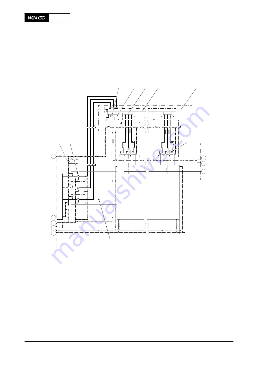
Fig 4-11
Fuel system with FLV (generic and simplified)
Cyl. n
59
51
67
ENGINE
PLANT
49
50
52
60
57
PLANT
ENGINE
001
002
003
004
005
006
007
008
009
Cyl. 1
Legend
001
Pressure control valve
006
Injection valve
002
Relief valve
007
Supply unit
003
Flow limiting valve (FLV)
008
Fuel pump
004
Fuel rail
009
Pressure retaining valve
005
Rail unit
X52
AA00-0000-00AAA-043E-A
Operation Manual
Fuel system
Winterthur Gas & Diesel Ltd.
- 90 -
Issue 002 2018-11
Содержание X52
Страница 8: ...Page left intentionally blank 8 ...
Страница 113: ...Page left intentionally blank 113 ...
Страница 275: ...7 Installation 7 1 Installation 276 275 ...
Страница 487: ...13 Schematic diagrams 13 1 Schematic diagrams general 488 13 2 List of diagrams 494 487 ...


