PROCEDURE
1
Do a check of the level switch LS3426A (if applicable also LS3427A) for free flow. If
necessary, clean the bore of the pipe of the level switch.
2
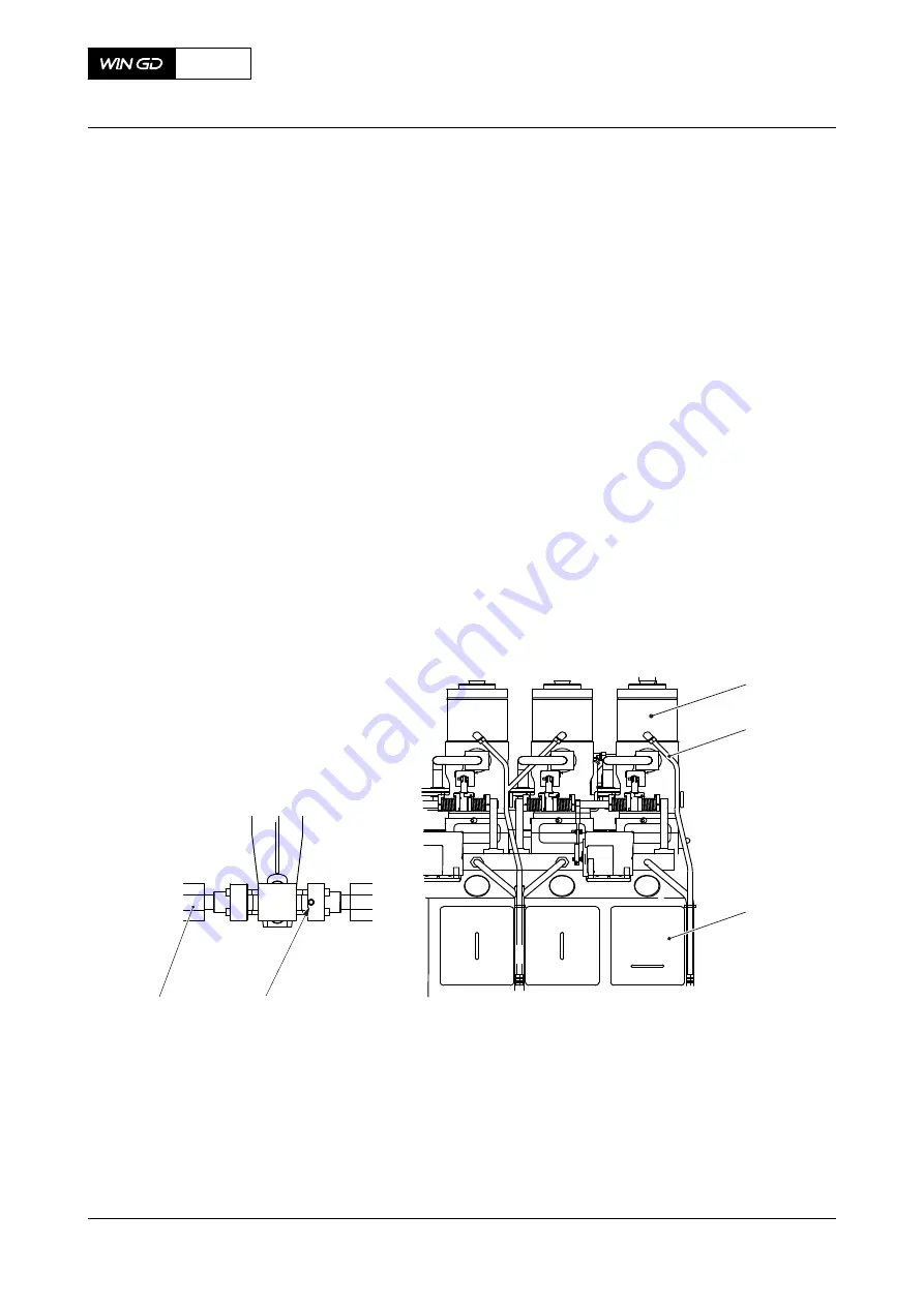
Carefully do a check of the temperature of the fuel leakage pipe (002,
) of each
fuel pump (001) to find the leakage pipe that has a fuel flow.
NOTE:
There is a fuel flow in the leakage pipe that has a higher temperature than the
other leakage pipes.
3
Continue with
to find the location of the leakage at the related fuel pump and its HP
fuel pipes.
4
Do a check of the HP fuel pipe (005) at the highest inspection point (004) for leaks.
4.1
Carefully loosen the screw plug a maximum of two turns.
4.2
Do a check for fuel flow.
4.3
If there is fuel flow, repair the cause of the fuel flow as soon as possible, refer to
the Maintenance Manual 8752-1.
NOTE:
The fuel system has high pressure. Replace a defective HP fuel pipe only
when the engine has stopped and the pressure in the system is released.
4.4
Tighten the screw plug.
Fig 10-2
Supply unit (example) and example of inspection point
001
002
003
004
005
Legend
001
Fuel pump
004
Inspection point
002
Fuel leakage pipe
005
HP fuel pipe
003
Supply unit
X52
AA00-0000-00AAA-311B-A
Operation Manual
Examine the supply unit for fuel leakage
Winterthur Gas & Diesel Ltd.
- 377 -
Issue 002 2018-11
Содержание X52
Страница 8: ...Page left intentionally blank 8 ...
Страница 113: ...Page left intentionally blank 113 ...
Страница 275: ...7 Installation 7 1 Installation 276 275 ...
Страница 487: ...13 Schematic diagrams 13 1 Schematic diagrams general 488 13 2 List of diagrams 494 487 ...


