PPC65BP-1x/Setup and Installation
v1.0
www.winsystems.com
Page 19
2. Connect optional components to the PPC65BP-1x as needed. For
example:
– Connect USB keyboard to a USB 2.0/3.1 Gen 1 port (connects to J12
or the I/O kit, as applicable).
– Connect an external monitor to DVI-I interface (connects to J15).
– Connect communications ports to an available COMM port
(connects to the I/O kit).
7.7
Mounting Method
Mount the PPC65BP-1x into a panel or a sub-frame of an industrial cabinet
using the provided panel mount holes and kits (see “Panel Mount” on
page 19), or a VESA compliant adapter plate (see “VESA Mount” on
NOTE To protect the PPC65BP-1x from dust and water, mount the system on a
non-textured surface.
7.7.1 Panel Mount
To install the PPC65BP-1x using a panel mount:
1. Verify or cut-out installation site using the following cut-out
dimensions. Refer to “Mechanical Drawings” on page 58 for model
specific drawings.
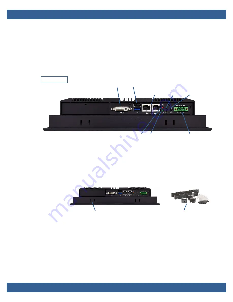
Bottom view
Selectable I/O kit
USB 2.0
USB 3.1 Gen 1
Gigabit
Ethernet
Reset
button
Power
button
DC in 12-24V via 3-pin
terminal block
Power LED
HDD LED
DVI-I
Panel mount holes
Panel mount clips
Содержание PPC65BP-1 Series
Страница 58: ...PPC65BP 1x v1 0 www winsystems com Page 58 Appendix B Mechanical Drawings PPC65BP 10 Dimensions...
Страница 59: ...PPC65BP 1x v1 0 www winsystems com Page 59 PPC65BP 12 Dimensions...
Страница 60: ...PPC65BP 1x v1 0 www winsystems com Page 60 PPC65BP 15 Dimensions...
Страница 61: ...PPC65BP 1x v1 0 www winsystems com Page 61 PPC65BP 17 Dimensions...
Страница 62: ...PPC65BP 1x v1 0 www winsystems com Page 62 PPC65BP 19 Dimensions...


