background image

5

5

5

5

6

6

6

3

4

3

2

X4

X4

X12

X1

Chart 3

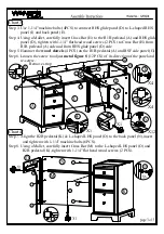
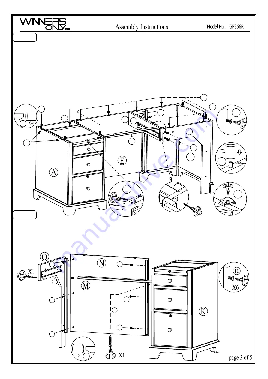
Step 3. Use 1-1/4" machine bolts (4PCS) to connect RHS glide panel (D) to L-shaped RHS
            panel (I) and back panel (E).
Step 4. Using a Mallet, carefully insert Cross Bar (H) to the R1B pedestal (A) and RHS glide
            panel (D), tighten with 1-1/4" flat head wood screws (2 PCS) to Cross Bar (H) from
            R1B pedestal (A) side and from RHS glide panel (D) side.
Step 5. Hammer the 

wood  dowels 

(4 PCS) on the R1B pedestal (A) and RSF side panel (G).

Step 6. Loosen the screw to adjust 

metal figure 8 

(12 PCS) of  its direction of the panel and

            re-screw.

H

D

I

G

4

X1

3

Remove strap

4

10

11

11

Chart 4

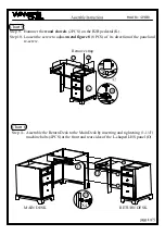
Step 7. Align the R2B pedestal (K) & L-shaped LHS panel (O) to the back panel (N),insert

              and tighten with 1-1/4" machine bolts (6PCS).

Step 8. Using a Mallet, carefully insert Cross Bar (M) to the L-shaped LHS panel (O) and

              R2B pedestal (K), tighten with 1-1/4" flat


head wood screws


(2 PCS).

10

10

10

11

10

10

Содержание GP366R

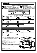
Страница 1: ... contact us Those are the non included tools needed to successfully assemble your new desk Phillips screw driver or Power Drill recommended Mallet IMPORTANT NOTE Please keep all hardware parts out of the reach of children RHS GLIDE PANEL BACK PANEL R1 DESK TOP B A 1 PC 1 PC C 1 PC R1B PEDESTAL E D 1 PC F 1 PC RSF SIDE PANEL CROSS BAR H G 1 PC 1 PC I 1 PC L SHAPED RHS PANEL R2 DESK TOP J 1 PC 1 PC ...

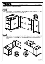
Страница 2: ...tal A back panel extension F to the back panel E insert and tighten with 1 1 4 machine bolts 6PCS Chart 2 Step 2 Align the back panel extension F to the RSF side panel G and the L shaped RHS panel I to the RSF side panel G insert and tighten with 1 1 4 machine bolts 6PCS 2 2 2 1 1 1 1 2 2 ...

Страница 3: ...from RHS glide panel D side Step 5 Hammer the wood dowels 4 PCS on the R1B pedestal A and RSF side panel G Step 6 Loosen the screw to adjust metal figure 8 12 PCS of its direction of the panel and re screw H D I G 4 X1 3 Remove strap 4 10 11 11 Chart 4 Step 7 Align the R2B pedestal K L shaped LHS panel O to the back panel N insert and tighten with 1 1 4 machine bolts 6PCS Step 8 Using a Mallet car...

Страница 4: ...he R2B pedestal K Step 10 Loosen the screw to adjust metal figure 8 8 PCS of its direction of the panel and re screw Remove strap Chart 6 Step 11 Assemble the Return Desk to the Main Desk by inserting and tightening 1 1 4 machine bolts 4PCS at the front and rear sides of the L shaped LHS panel O ...

Страница 5: ...4 13 X20 X3 X2 H D 12 X2 Chart 7 Step 12 Place R1 desk top B and R2 desk top J over the bases Connect RHS glide panel D to R1desk top B by inserting 1 1 4 machine bolts 3 PCS but do not fully tighten Align both tops to each other and fully tighten previously inserted 1 1 4 machine bolts 3 PCS Use 1 1 4 flat head wood screws 2pcs to reinforce the assembly Step 13 Insert short 3 4 flat head wood scr...

Отзывы: