


USER MANUAL
CHAPTER 2
HARDWARE INSTALLATION
- 20 -
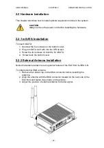
CHAPTER 2: HARDWARE INSTALLATION
This chapter provides information on how to use external I/O and the installation
of EAC Mini IL20EAC-N IoT Gateway hardware.
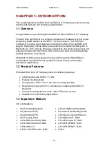
2.1 Connectors
This section describes all the external connectors located on the EAC Mini
IL20EAC-N IoT Gateway.
The following sections give you information about EAC Mini IL20EAC-N standard
connectors and pin assignments.
2.1.1 HDMI Connector
Plug HDMI signal cable to the HDMI connector of the EAC Mini IL20EAC-N, and
plug the other end to the monitor.
Pin Assignment and signal names for HDMI connector
2.1.2 Ethernet Connector
The EAC Mini IL20EAC-N has two Ethernet connectors located on the front.
Ethernet ports provide a standard RJ45 10/100/1000 Mbps jack connector with
LED indicators on the front side to show its Active/ Link status and Speed status.
10/100 Mbps- Green
1G Mbps
– Orange
Pin №
Signal Name
Pin №
Signal Name
1
H
2
GND
3
HDMI_RX2-
4
H
5
GND
6
HDMI_RX1-
7
H
8
GND
9
HDMI_RX0-
10
H
11
GND
12
HDMI_RXC-
13
HDMI_CON_CEC
14
NC
15
HDMI_CON_SCL
16
HDMI_CON_SDA
17
HDMI_CON_CABLE
18
+5V_HDMI
19
HDMI_CON_HP
Pin №
Signal Name
Pin №
Signal Name
1
TX1+
2
TX1-
3
TX2+
4
TX3+
5
TX3-
6
TX2-
7
TX4+
8
TX4-
Содержание EAC Mini IL20EAC-N
Страница 1: ...IoT Gateway Intel Apollo Lake N3350 1 1 GHz EAC Mini IL20EAC N User Manual Version 1 0 ...
Страница 2: ......
Страница 37: ...USER MANUAL CHAPTER 4 INSYDE UEFI BIOS SETUP 35 4 2 2 2 GOP and IGD Configuration ...
Страница 41: ...USER MANUAL CHAPTER 4 INSYDE UEFI BIOS SETUP 39 PCI Express Root Port ...
Страница 43: ...USER MANUAL CHAPTER 4 INSYDE UEFI BIOS SETUP 41 4 2 2 4 SATA Drives ...
Страница 57: ...USER MANUAL CHAPTER 4 INSYDE UEFI BIOS SETUP 55 4 2 3 Boot Menu ...
Страница 59: ...USER MANUAL CHAPTER 4 INSYDE UEFI BIOS SETUP 57 4 2 3 1 Boot Type Order 4 2 3 Exit Menu ...


