3
6
AMPLIFIED MODEL SS-2000 ONLY
Attaching Downlead Cable
NOTE: A diplexer that is power
passive on both sides may be
used instead of the power supply.
If using diplexer, connect coax to
diplexer secured on back of an-
tenna with velcro (supplied).
If using the power supply, follow
these steps.
STEP 6. Attach "F" connector to
downlead and connect to "F" jack on
power supply marked "TO
PREAMP". See Figure 4.
STEP 7. Attach "F" connector to
cable from HDTV signal or analog
signal inputs and connect to "F" jack
on power supply marked "TO TV".
See Figure 4.
STEP 8. Mount the two #6 screws
vertically 3-1/4" apart leaving screw
heads approximately 1/8" from wall.
See Figure 5.
STEP 9. Hang power supply onto
screws and plug power supply AC
power cord into receptacle.
CAUTION:
No splitters or couplers should be
installed in the coax line between
the antenna and the power supply.
Figure 4
Figure 5
NOTICE: FAILURE TO PROPERLELY CONNECT
CABLES MAY RESULT IN DAMGE TO TV SET.
TO PREAMP
TO TV
U.S. Pat. No. D355,887, D358,365,
5,515,240 Power supply housing
design.
3-1/4"
#6x1/2
Screws
15. Do not overload wall outlets and extension cords
as this can result in a risk of fire or electric shock.
16. Never push objects of any kind into this video
product through openings as they may touch danger-
ous voltage points or short-out parts that could result
in a fire or electric shock. Never spill liquid of any kind
on the video product.
17. Do not attempt to service this video product
yourself as opening or removing covers may expose
you to dangerous voltage or other hazards. Refer all
servicing to qualified service personnel.
18. Unplug this video product from the wall outlet and
refer servicing to qualified service personnel under
the following conditions:
a. When the power supply cord or plug is damaged.
b. If liquid has been spilled or objects have fallen into
the video product.
c. If the video product, except for antenna mounted
preamplifiers and downconverters, has been exposed
to rain or water.
d. If the video product does not operate normally by
following the operating instructions. Adjust only those
controls, when provided, that are covered by the
operating instructions. An improper adjustment of
other controls may result in damage that will often
require extensive work by a qualified technician to
restore the video product to its normal operation.
e. If the video product has been dropped or the
housing has been damaged.
f. When the video product exhibits a distinct change in
performance - this indicates a need for service.
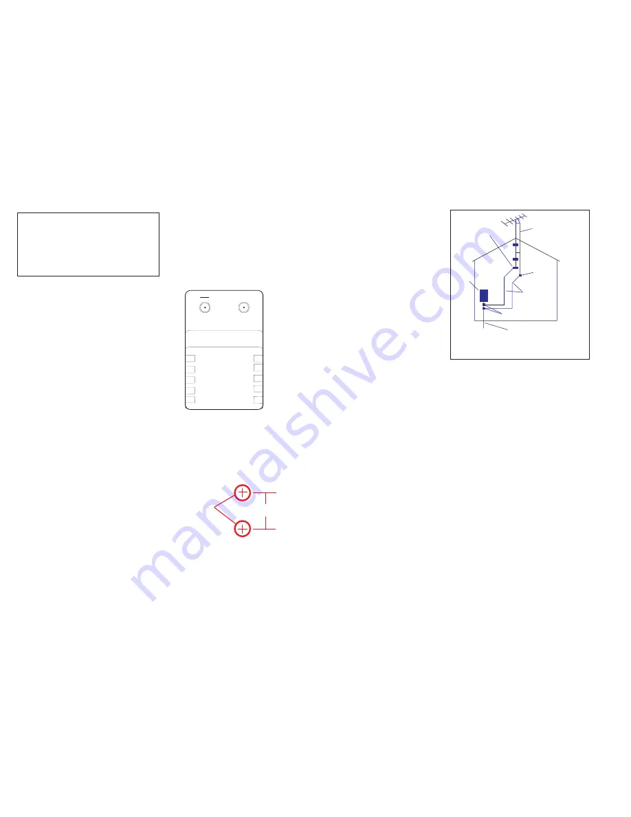
EXAMPLE OF ANTENNA
GROUNDING IN
ACCORDANCE WITH THE
NATIONAL ELECTRICAL CODE
INSTRUCTIONS
19. When replacement parts are required, be sure
the service technician has used replacement parts
specified by the manufacturer or have the same
characteristics as the original part. Improper sub-
stitutions may result in fire, electric shock or other
hazards.
20. Upon completion of any service or repairs to
this video product, ask the service technician to
perform safety checks to determine that the video
product is in proper operating condition.
21. Note to CATV system installer: This reminder
is provided to call the CATV system installer's
attention to Art. 820-40 of the NEC that provides
guidelines for proper grounding and, in particular,
specifies that the cable ground shall be connected
to the grounding system of the building, as close
to the point of cable entry as possible.
22. This product should be mounted to a wall or
ceiling only as recommended by the manufac-
turer.
23. The product should be situated away from
heat sources such as radiators, heat registers,
stoves or other products (including amplifiers)
that produce heat.
ä
Antenna Discharge Unit
(NEC Section 810-21)
ä
ä
ä
ä
ä
Ground Clamps
Grounding Conductors
(NEC Section 810-21)
Power Service Grounding
Electrode System
(NEC Art. 250, Part N)
ä
Antenna
Lead-in Wire
Ground Clamp
Electrical
Service
Equipment
ä
ä
ä
NEC - NATIONAL ELECTRICAL CODE


