Windsor TRACER FS QTFSD Скачать руководство пользователя страница 19

MAINTENANCE

QTFSG/QTFSD  98349  05/15/03

4-2

HYDRAULIC FILTER

The hydraulic filter keeps the machines hydraulic
system clean to a level of 10 microns.  The hydraulic
fluid filter is located just inside the left rear frame.
The filter should be changed every 500 hours.

TO REPLACE FILTER ELEMENT:

1. 

Stop the engine and set the parking brake.

2. 

Open the seat support.

3. 

Unthread and discard the hydraulic fluid filter
element.

4. 

Apply a thin coat of hydraulic fluid to the seal of
the new hydraulic fluid filter element.

5. 

Thread and hand tighten the new hydraulic fluid
filter element on the filter head.

6. 

Close the seat support.

7. 

Operate the machine and check for leaks.
Correct any leaks found.

8. 

Check the hydraulic fluid reservoir level and fill
as required.

DIRECTIONAL CONTROL SYSTEM
(Refer to the Electrical Control Group


in the

Parts section)

The directional control system controls the direction
and speed of the machine.  The system is made up
of the directional pedal, the throttle box, the
transistorized controller and contactors.  The
controller, located in the electrical drive
compartment, is sealed and can only be serviced by
trained service personnel.

Do not use a pressure washer to clean the inside
of the electrical drive compartment.

When servicing machine, disconnect battery
connections before working on machine.

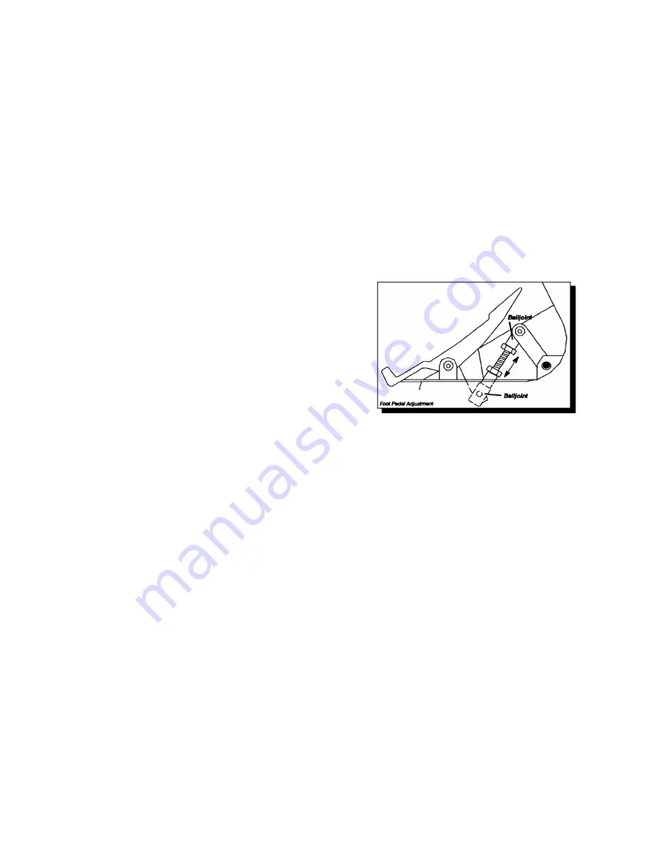
DIRECTIONAL CONTROL PEDAL ADJUSTMENT
(Refer to the Console Group in the Parts section)

The directional control pedal is designed to prevent
driver fatigue.  However if a different pedal angle is
preferred, these directions should be followed.

1. 

Raise rear cover.

2. 

Disconnect batteries from machine.

3. 

Locate and remove the directional control pedal
stop bolt.

4. 

Locate the linkage rod beneath the directional
control pedal.

5. 

Adjusting the length of the linkage rod controls
the pedal angle.  Shortening the linkage rod
causes the pedal to have a flatter angle with the
floor.  Lengthening the linkage rod causes the
pedal to have a steeper angle.

6. 

To change the length of the linkage rod,
disconnect the upper end of the linkage rod from
the forward/reverse arm.

7. 

Loosen the locking nuts on both ends of the
threaded portion of the linkage rod.

8. 

Turning the balljoint changes the length of the
linkage rod, be sure that there is a minimum of
5/16” of threaded rod engaged in each of the
balljoints.

9. 

When the new length is established, reconnect
the upper balljoint to the forward/reverse arm.

10. 

Tighten the two locking nuts on the threaded
portion of the linkage rod.

11. 

Reposition the directional foot pedal stop bolt.

12. 

The stop bolt must be adjusted so that the
directional foot pedal comes in contact with the
stop while there is still a small amount of travel
remaining in the throttle arm.  This is done to
prevent heavy foot pressure from damaging the
throttle unit.

THROTTLE “NEUTRAL POSITION”
ADJUSTMENT (Refer to the Console Group in
the Parts section)

The throttle is automatically returned to its neutral
position by a spring centering system.  If the
machine tends to creep forward or reverse when the
operators foot is removed from the directional foot
pedal, the throttle “neutral position” may require
adjustment as described below:

1. 

Turn off machine and set parking brake.

2. 

Raise the rear cover.

3. 

Disconnect the batteries from the machine.

4. 

Remove the drive motor dust cover.

5. 

Locate the throttle and spring centering
assembly.

6. 

Disconnect the linkage rod from the throttle arm.

7. 

With the throttle arm free, the throttle will return
to its neutral position using its internal centering
spring.

8. 

Position the linkage rod balljoint over the hole in
the throttle arm.  The balljoint should slide into
the hole without repositioning the throttle arm.

9. 

If required, shorten or lengthen the linkage rod
until proper engagement occurs.

10. 

Reattach linkage rod to the throttle arm.

11. 

Install the drive motor dust cover.

12. 

Connect batteries.

13. 

Lower hopper.

Содержание TRACER FS QTFSD

Страница 1: ...MODEL TRACER FS QTFSD Diesel Version QTFSG Gas Version Operating Instructions 98349 11 01 03 M FLOOR SWEEPER Read these instructions before using the machine IPX4...

Страница 2: ...______ MODEL _______________________________________ DATE OF PURCHASE __________________________ SERIAL NUMBER ______________________________ SALES REPRESENTATIVE _____________________ DEALER NAME ___...

Страница 3: ...ttery Information 4 14 Hydraulic Schematic 4 15 Hydraulic Troubleshooting 4 15 Propelling Troubleshooting 4 16 Machine Troubleshooting 4 17 Service Schedule 4 18 GROUP PARTS LIST Frame Group 5 1 Diffe...

Страница 4: ...ydraulic Troubleshooting Propelling Troubleshooting Machine Troubleshooting Service Schedule The PARTS LIST section contains assembled parts illustrations and corresponding parts list The parts lists...

Страница 5: ...ial use for example in hotels schools hospitals factories shops and offices for more than normal housekeeping purposes Maintenance and repairs must be done by qualified personnel During operation atte...

Страница 6: ...stood In Flammable or Explosive areas In areas with possible falling objects WHEN SERVICING MACHINE Avoid moving parts Do not wear loose clothing jackets shirts or sleeves when working on the machine...

Страница 7: ...CATION QTFSG QTFSD 98349 05 15 03 2 3 NOTE These drawings indicate the location of safety labels on the Tracer FS If at any time the labels become illegible contact your Windsor representative for pro...

Страница 8: ...CATION QTFSG QTFSD 98349 05 15 03 2 4 NOTE These drawings indicate the location of safety labels on the Tracer FS If at any time the labels become illegible contact your Windsor representative for pro...

Страница 9: ...um Speed 10k hour Sweep Path 1200mm Main Broom 812mm Main Broom Diameter 355mm Side Broom 510mm Hopper Capacity 180 liters Hopper Dump 1520mm Dust Control 54ft2 5m2 pleated filter with exclusive cyclo...

Страница 10: ...was a tri axial third octave band measurement made during normal operation on a composite tile floor The measurement and related calculations were made in accordance with ANSI S3 34 1986 SPECIAL NOTE...

Страница 11: ...in Broom Lever G Side Broom Lever H Filter Shaker Switch I Hopper Door Switch J Hopper Lift Switch K Hopper Safety Arm L Engine Temperature Light M Oil Pressure Light N Engine Glow Plug Light Diesel O...

Страница 12: ...cover back To close the rear cover lower it slowly until the latch engages the floor slot Do not let the rear cover drop or damage to the latch or cover may occur FOR SAFETY When the rear cover is op...

Страница 13: ...e engine is overheating If the light comes on stop the engine immediately and determine the cause Failure to stop the engine will result in engine damage Some causes of engine overheating are a clogge...

Страница 14: ...ROTECTED CB 1 30A Voltage Regulator CB 2 15A Igniter Fuel Pump Oil Pressure Lamp Water Temp Lamp CB 3 15A Side Broom Valve Head Lamps Tail Lamps Horn CB 4 15A Options CB 5 15A Hopper Dump Door Shaker...

Страница 15: ...switch clockwise to the ON position 3 Drive the machine to the area where sweeping is to begin TO SWEEP Plan the sweeping pattern in advance For efficient operation the sweeping runs should be long w...

Страница 16: ...ean the filter by pressing the filter shaker switch for 10 20 seconds 2 Close the hopper door by pushing and releasing the front half of the hopper door switch The beeper will sound 3 Press and hold t...

Страница 17: ...e FOR SAFETY Before leaving or servicing machine stop on level surface set parking brake turn off machine and remove key 3 Block the tires that are not being raised to prevent the machine from rolling...

Страница 18: ...eplaced every 500 hours of use To drain hydraulic reservoir 1 Turn off machine and set parking brake FOR SAFETY Before leaving or servicing the machine stop on level surface apply parking brake turn o...

Страница 19: ...uses the pedal to have a flatter angle with the floor Lengthening the linkage rod causes the pedal to have a steeper angle 6 To change the length of the linkage rod disconnect the upper end of the lin...

Страница 20: ...level surface apply parking brake turn off the machine and remove key 2 Raise rear cover 3 Disconnect batteries from machine 4 Lower the main broom lever 5 Open the right side broom door 6 Remove the...

Страница 21: ...ut 9 Check the broom pattern again Repeat the procedure until the pattern is correct A Main Broom Pattern B 1 to 1 1 2 25 4 to 38 1mm NOTE If one end of the main broom pattern is more than 1 2 12 7mm...

Страница 22: ...he side broom retaining pin 6 Push up on the base of the side broom to relieve the tension on the retaining pin then remove the retaining pin 7 Slide the side broom off the side broom motor shaft TO I...

Страница 23: ...pling then lift the shaft up to remove drive belt in reverse order 16 Reinstall belt in reverse order ADJUSTING THE JACKSHAFT BELT Proper alignment is important for all belts on Tracer machines To pro...

Страница 24: ...e pulley located on the rear jackshaft 9 Slide pulley side to side to align with main broom drive pulley below 10 Retighten setscrews in pulley 11 Reverse Steps 1 7 NOTE This adjustment may require re...

Страница 25: ...off machine and remove key 3 Raise rear cover 4 Disconnect batteries from machine 5 Remove the drive motor dust cover 6 Loosen 4 bolts holding transmission case to mount 7 Locate tensioning bolt at to...

Страница 26: ...e Group and the Main Broom Group in the Parts section The main broom skirts prevent dust from exiting the main broom chamber The skirts should be inspected for wear or damage daily When correctly adju...

Страница 27: ...adjustment nuts 6 Tighten the five broom skirt 7 Adjust the rear skirt ADJUSTING THE REAR BROOM SKIRT 1 Turn off machine and set parking brake FOR SAFETY Before leaving or servicing machine stop on l...

Страница 28: ...e FOR SAFETY Before leaving or servicing machine stop on level surface apply parking brake turn off machine and remove key 4 Loosen the three adjustment bolts 5 Adjust the hopper side seals for correc...

Страница 29: ...and set parking brake FOR SAFETY Before leaving or servicing machine stop on level surface apply parking brake turn off machine and remove key 4 Check the distance from the lower rear edge of the hopp...

Страница 30: ...o front tire disc brakes The disc brakes should be checked every 200 hours of operation and adjusted if necessary The disc brakes should be adjusted so that the disc pads are as close to the brake dis...

Страница 31: ...ocated under the engine center of frame When removing the battery cables remove the negative cable before removing the positive cable When servicing machine avoid contact with acid Batteries emit hydr...

Страница 32: ...Clean or replace orifice located behind the lower cylinder fitting Pump solenoid failure Replace pump solenoid Check valve failure Replace check valve or solenoid Lift cylinder failure Replace cylinde...

Страница 33: ...lure Replace main contactor Key operated on off switch failure Replace on off switch Chain failure Repair chain Machine moves without pressing foot pedal Throttle not set at neutral position Adjust li...

Страница 34: ...caught in broom drive mechanism Free mechanism of debris Main broom drive failure Belt loose broken or off pulley Side broom drive failure Check circuit breaker Check side broom motor circuit Hopper...

Страница 35: ...m side broom adjustment remove string etc check for damage Check main broom skirts and seals Check hopper lip skirts for damage and wear Visually check tires for damage and proper inflation Check for...

Отзывы: