background image

19

OPM-117/D

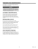
Reasonable care in preventative maintenance will ensure 

high reliability and a long life for the engine-generator set 

and Automatic Transfer Switch.

WARNING:

When performing any type of maintenance on this 

equipment, make sure the selector switch on the engine-

generator is in the off position. If you are working in the 

Automatic Transfer Switch, confirm with a reliable meter 

that all power has been disconnected.

AUTOMATIC TRANSFER SWITCH

Clean and inspect the switch once a year. De-energize 

all power sources, both line and engine-generator set, 

then brush and vacuum away any excessive dust or 

dirt accumulation. At this time, with the conductor de-

energized, you can remove the contact covers and check 

the contacts. Make sure contacts are clean and not burned 

or pitted.

ENGINE-GENERATOR SET

Service the engine in accordance with the engine 

manufacturer’s manual provided with your new equipment. 

Routinely remove debris and dirt from around the inside 

generator enclosure. Ensure that the air intakes are free 

from leaves and other debris at all times.

Clean and inspect battery terminals at least twice a year. 

Also check the battery water level at least twice a year.

Other than keeping the generator clean and free of debris, 

there is no other routine or preventative maintenance 

required as long as the generator is run bi-weekly to keep it 

dry and in good working order.

COLD WEATHER OPERATION

Extreme cold weather operation requires special 

considerations. Higher CCA batteries are required for cold 

weather starting; 650 CCA or larger are recommended. In 

addition, you should consider installing an oil heater kit and 

a battery warmer for reliable starting during cold weather.

PREVENTATIVE MAINTENANCE

Содержание PSS60/E

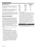
Страница 1: ...r need to contact us on this unit it will help us to respond to your needs faster MODEL __________________________________________________ SERIAL NUMBER _________________________________________ PURCHASE DATE _________________________________________ DEALER NAME ___________________________________________ DEALER PHONE ________________________________________ www wincogen com 16200 016 ...

Страница 2: ...L PRESSURE TABLES NG LP FUEL CONVERSION INSTALLING THE BATTERY 11 SERVICING BATTERIES BATTERY CHARGING CONNECTING THE BATTERY CHARGER BLOCK HEATER AC ELECTRICAL CONNECTIONS 13 GROUNDING MOUNTING THE ATS DC ELECTRICAL INTERCONNECTION 15 ASCO 185 UL SWITCH ASCO 300 UL SWITCH INITIAL START UP STARTING PROCEDURE 17 VOLTAGE REGULATOR WIRING 18 AUTOMATIC TRANSFER SWITCH ENGINE GENERATOR SET COLD WEATHER...

Страница 3: ...NCO generator You have selected a high quality precision engineered generator designed and tested to give you years of satisfactory service To get the best performance from your new generator it is important that you carefully read and follow the operating instructions in this manual Should you experience a problem please follow the Troubleshooting Tables near the end of this manual The warranty l...

Страница 4: ...esent a hazard of possible explosion and or fire A Do not refuel when the engine is running or hot B Keep fuel containers out of reach of children C Do not smoke or use open flame near the generator set or fuel tank D Keep a fire extinguisher nearby and know its proper use Fire extinguishers rated ABC by NFPA are appropriate E Store fuel only in an approved container and only in a well ventilated ...

Страница 5: ...ms Per Ph 20 C Exciter Stator L L 20 00 Ohms 20 C Aux Winding 2 6 Ohms 20 C Voltage Regulator L L AS440 PSS90 E PSS90 F LP Gas Wattage 80 000 80 000 80 000 80 000 Volts 120 240 120 208 120 240 277 480 kvA 80 100 100 100 Phase Single Three Three Three Amps 333 278 240 120 CB Size 400 300 300 150 Hertz 60 60 60 60 Natural Gas Wattage 90 000 90 000 90 000 90 000 Volts 120 240 120 208 120 240 277 480 ...

Страница 6: ...r outside installation The transfer switch is UL1008 approved A fourteen day electronic exerciser circuit is installed in the ATS as standard equipment The ATS also contains the power failure sensing circuitry necessary to start and stop the engine generator set The transfer switch is also equipped standard with a 3 second start delay and a 15 second transfer delay to allow the engine to warm up b...

Страница 7: ...e received is the correct model and review the specification pages in this manual to ensure that this unit meets your job requirements CAUTION EQUIPMENT DAMAGE These units are shipped with oil and a 50 50 mix of coolant Be sure to check all fluid levels before operating See engine manufacturer s instruction manual for recommended oil requirements before initial starting Once generator set is on si...

Страница 8: ...ator to the generator set INSTALLATION WARNING Before proceeding with installation be sure the operation selector switch is in the stop position and the battery disconnected These engine generator sets are designed to be mounted on a pad where there is proper ventilation The transfer switch is mounted next to your electrical entrance or distribution panel inside or outside the building Consult a q...

Страница 9: ... withdrawal a primary regulator is not required on the supply tank The supply line is connected to a liquid withdrawal valve on the supply tank and runs directly to the fuellock strainer mounted on the engine generator set Normally a 3 8 to 1 2 inch copper line is acceptable for this type of fuel installation You must be sure that the valve you have connected to on the supply tank is in fact a liq...

Страница 10: ...he necessity of using the correct oil and keeping the crankcase full cannot be over emphasized Failure to do so will cause excessive engine wear and shorten its useful life Before starting the engine Check the coolant level in the radiator If it is low refill as specified in the engine manufacturer s maintenance instructions The radiator should be filled to about 1 inch below the filler neck The f...

Страница 11: ...ttery terminal is connected to the negative cable ground from the engine generator assembly All connections must be clean and tight Check the electrolyte fluid in the battery periodically to be sure it is above the plates Never allow the battery to remain in a discharge condition INSTALLING THE BATTERY CAUTION In the following battery installation procedure check to be sure the selector switch rem...

Страница 12: ...on without over charging them During this stage the green LED is constantly lit There are optional 5 and 10 amp chargers available that may be installed on some units The block heater is thermostatically controlled and when plugged in will maintain the engine coolant temperature between 100 and 120 degrees F NOTICE The trickle charger is not intended to recharge a battery which has become complete...

Страница 13: ...el protecting the contactor switch All wires should be installed in rigid or flexible conduit knockouts are provided in the control box GROUNDING A grounding lug has been provided on the engine generator set Check your local codes for proper grounding requirements NOTICE CLASS 1 WIRING METHODS ARE TO BE USED FOR ALL FIELD WIRING CONNECTIONS TO TERMINAL OF A CLASS 2 CIRCUIT WARNING A mainline circu...

Страница 14: ...d in the emergency distribution panel The A T S is then installed between the main panel and the emergency distribution panel Suggested circuits freezer refrigerator furnace emergency lights sump pump emergency outlet circuits etc Total running load must not exceed generator rating WARNING A service disconnect must be installed in front of the ATS panel as the ATS is not service entrance rated Thi...

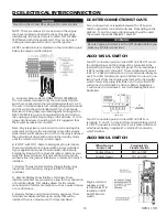
Страница 15: ...y charger to DSE7310 MKII controller D Remote Display Panel Interface Terminals These interface terminals are pre wired to allow for the connection of a remote display This display allows for the remote annunciation of alarms at a location such as a nurses station or a control room E Battery Positive and Ground battery negative These terminals are dedicated for any accessory that will be installed...

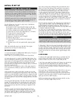
Страница 16: ...ncy on the digital display The voltage should be 208 240 480 AC depending on which model you have and a frequency of 59 5 to 60 5 hertz Hz If you have the proper voltage at the generator the next step is to check the voltage at the generator terminals in the Automatic Transfer Switch The voltage between the G1 and the G3 terminals should be the same as it was on the generator front panel The volta...

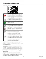
Страница 17: ...ce as a lamp test function MENU NAVIGATION Used for navigating the instrumentation event log and configuration screens A small rocker switch is located on the underside of the engine control cabinet On gaseous models the engine timing is controlled by the ECU on the engine and you need to tell it what fuel you want to operate on LP or NG On diesel models this switch has been disconnected and will ...

Страница 18: ... effect 4 LINK POWER RESPONSE A B 550kW Fast B C 100 550kW Fast A C 100kW Fast B D 100kW Slow 5 UFRO Under Frequency Roll Off Clockwise decreases KNEE point 6 SWITCH Select alternator frequency for UFRO SWITCH LEFT 60Hz SWITCH RIGHT 50Hz 7 LED Indicator Light LED light on in UFRO or O EXC condition 8 DROOP Adjust alternator droop to 5 at zero power factor Clockwise to increase increase droop 9 TRI...

Страница 19: ... and not burned or pitted ENGINE GENERATOR SET Service the engine in accordance with the engine manufacturer s manual provided with your new equipment Routinely remove debris and dirt from around the inside generator enclosure Ensure that the air intakes are free from leaves and other debris at all times Clean and inspect battery terminals at least twice a year Also check the battery water level a...

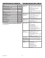
Страница 20: ...ust hold 12 Volts during cranking 2 Blown fuse on generator control panel 3 Loose or dirty battery terminals 4 Defective engine control module 5 Defective starter 6 Defective start solenoid 7 Locked up engine generator set ENGINE WILL NOT COME UP TO SPEED AFTER IT STARTS 1 Insufficient fuel volume getting to the unit a Fuel line too small b Low fuel pressure 2 AC short circuit 3 Defective ECU on t...

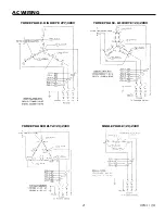
Страница 21: ...5 HIGH AND LOW WYE THREE PHASE LOW WYE 120 208 VOLTS THREE PHASE HIGH WYE 277 480 VOLTS THREE PHASE HIGH WYE 277 480V THREE PHASE LOW WYE 120 208V THREE PHASE DELTA 120 240 VOLTS THREE PHASE AC WIRING DELTA AC D THREE PHASE DELTA 120 240V 5060 00 60708 165 T 1 TH W SINGLE PHASE 120 240 VOLTS SINGLE PHASE AC WIRING 4 LEAD SINGLE PHASE 120 240V ...

Страница 22: ...7 D ENGINE HARNESS SCHEMATIC 6 1 6 1 1 3 6 237 21 2 22 17 6 1625 3 8 3 8 1 1 8 8 62 12 6 67 57 200 1 8 6 7 1 7 21 1 2 1 5 9 51 3 5 0 0 7 6 5 1 217 16 35235 7 5 1 250 7 21 21 1 72 1 2 81 87 25 86 6 352 7 0 7 72 5 ...

Страница 23: ...1 77 77 1 5 7 50 1 2 6 211 725 211 725 66 86 86 86 86 86 36 1 2 8 1387 20021 6 5 1 1 6 5 1 1 1 1 1 36 32 5 6 7 66 0 5 1 6723 6 7 66 8 6 7 21 6 7 9 5 92 7 8670 17 5 267 7 9 5 ƺ 1 855 17 66 7 50 1 2 803 56 6 2 1 29 25 2 7 5 255 6321 1 7 50 1 6 5 9 6 216 5 9 51 6 5 37 21 7 33 5 9 6 21 2 21752 5 6 5 83 7 7 5 567 3 27 8 6 5 36 8 21752 83 7 287387 6 5 1 335 7 7 6 0 1 1 21752 7 7 7 5 1 02 3 57 6 7 6 5 1 ...

Страница 24: ...component of the product that is no longer manufactured or available Additionally WINCO Inc will not be liable for any engine replacement that may require an emissions tier level change THERE ARE NO EXPRESS WARRANTIES OTHER THAN THOSE DESCRIBED HEREIN THERE ARE NO OTHER WARRANTIES EXPRESSED OR IMPLIED OR OTHERWISE CREATED UNDER THE UNIFORM COMMERCIAL CODE INCLUDING BUT NOT LIMITED TO WARRANTIES OF...

Отзывы: