


© by WilTec Wildanger Technik GmbH
Seite 12
http://www.wiltec.info
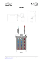
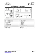
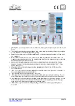
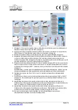
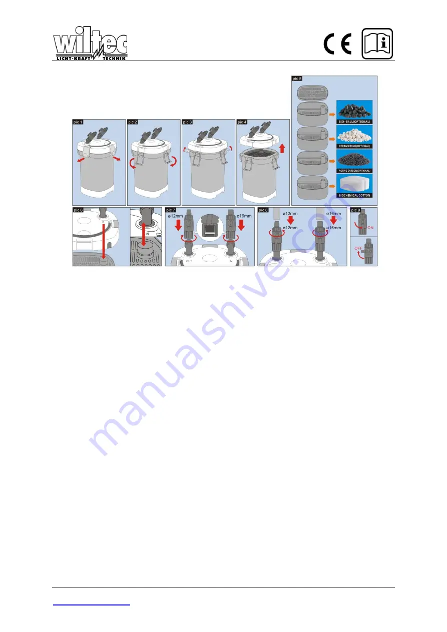
1. (Pic 1) Pull-
up 4 clasps due to arrow‟s direction, making the clasps depart from the cover
(pic 2).
2.
. There are two handles on the cross of filter body, hold the handle‟s bottom then pull up
(pic 3), filter cover and body departed (pic 4).
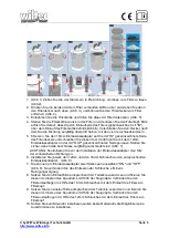
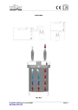
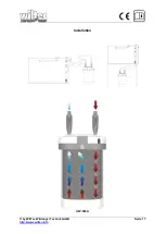
3. Take out the filter box, put in filter materials or bio-cottons due as you like, pls find (pic5)
for reference.
4. Put back the full filter box in turn, put on cover. Pls pay attention, the inlet of filter box
must
be same direction with the “IN” mark on the cover (pic 6), close and make sure it is
sealed well, then put down 4 clasps.
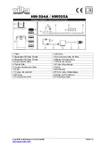
5.
Connect 16 in/outlet adjuster on bend connector where there is marked “IN”, Screw
down it. Connect 12 in/outlet adjuster on bend conn
ector where marked “OUT”, then
screw down (pic 7).
6. Attention: Before connect above in/outlet adjuster, pls check if the O RING on the
connector is well.
7. . Put tube 16mm into 16 in/outlet adjuster and screw down, then put tube 12mm into 12
in/outlet adjuster and screw down (pic 8).
8. . Pls see the swift of in/outlet adjuster on (pic 9).
9. . Pls assemble the inlet parts according to the dismantle pic, and put in orderly, then fix
them inside tank by sucker. Put tube 16mm into inlet bend connector and screw down.
10. . Pls assemble the outlet parts according to the dismantle pic, and put in orderly, then fix
them in tank by sucker. You can decide the direction and height by yourself, then put
tube 12mm into outlet bend connector and screw down.
11. . There has a jet connec
ted outlet parts, if you don‟t want scatter pipe, then jet can
replace it.
Содержание 50370
Страница 4: ... by WilTec Wildanger Technik GmbH Seite 4 http www wiltec info Installation HW 505A ...
Страница 11: ... by WilTec Wildanger Technik GmbH Seite 11 http www wiltec info Installation HW 505A ...
Страница 17: ... by WilTec Wildanger Technik GmbH Seite 17 http www wiltec info Installation HW 505A ...


