


en
Commissioning
18
WILO SE 2019-02
Wire colour
Terminal
Brown (bn)
L
Blue (bu)
N
Green/yellow (gn-ye) Earth
The single-phase current version is equipped with a shockproof
plug. The connection to the mains is established by inserting the
plug into a socket. The plug is
not
overflow-proof.
Install the
socket so that it is overflow-proof!
Observe the information on
the protection class (IP) of the plug.
DANGER! If the pump is connected directly to the switchgear,
dismantle the plug and arrange for the electrical connection to
be carried out by a qualified electrician!
6.5.4
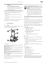
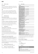
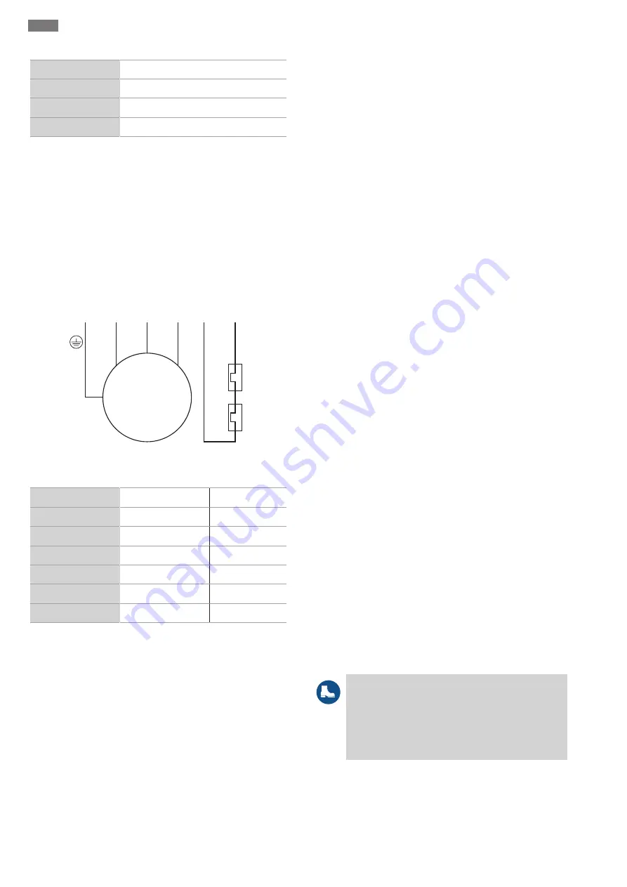
Three-phase current motor connection
W 5
1
2
V 4
U 3
M 3~
gn-y
e
L3
L2
21
20
L1
PE
250 V (A
C); 2,5 A; cos φ = 1
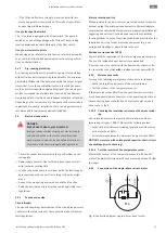
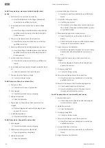
Fig. 9:
Connection diagram three-phase current motor
Wire number
Designation
Terminal
1
20
WSK
2
21
WSK
3
U
L1
4
V
L2
5
W
L3
Green/yellow (gn-ye) Earth
PE
For three-phase current motors, a clockwise rotating field must
be available. The three-phase current version is equipped with a
CEE plug or with a bare cable end:
ƒ
If a CEE plug is supplied, connection to the mains is estab-
lished by inserting the plug into a socket. The plug is
not
overflow-proof.
Install the socket so that it is overflow-
proof!
Observe the information on the protection class (IP) of
the plug.
ƒ
If there is a bare cable-end, the pump must be connected dir-
ectly to the switchgear.
DANGER! If the pump is connected
directly to the switchgear, arrange for the electrical con-
nection to be carried out by a qualified electrician!
6.5.5
Monitoring device connection
All monitoring device must be connected!
6.5.5.1 Monitoring of motor winding
Single-phase current motor
Thermal motor monitoring is self-switching for single-phase cur-
rent motors. The monitoring function is always active and does
not need to be connected separately.
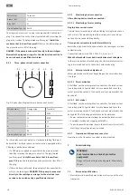
Three-phase current motor with bimetallic strip
Bimetallic strips are directly connected to the switchgear or via an
evaluation relay.
Connection values: max. 250 V (AC), 2.5 A, cos φ = 1
When the threshold is reached, deactivation must take place.
In the version with an attached plug, the thermal motor monitor-
ing is pre-wired and set to the correct value in the plug.
6.5.6
Motor protection adjustment
Motor protection must be set depending on the selected activa-
tion type.
6.5.6.1 Direct activation
At full load, set the motor protection switch to the rated current
(see rating plate). At partial load, it is recommended to set the
motor protection switch 5 % above the current measured at the
duty point.
6.5.6.2 Soft starter
At full load, set the motor protection switch to the rated current
(see rating plate). At partial load, it is recommended to set the
motor protection switch 5 % above the current measured at the
duty point. The following points must also be observed:
ƒ
Power consumption must always be below the rated current.
ƒ
Complete starting and stopping within 30 s.
ƒ
To avoid power dissipation, bypass the electronic starter (soft
start) once normal operation is reached.
6.5.7
Operation with frequency converter
Operation on the frequency converter is not permitted.
7
Commissioning
WARNING
Foot injuries due to a lack of protective
equipment!
Danger of (serious) injuries during work. Wear safety
shoes!
7.1
Personnel qualifications
ƒ
Electrical work: A qualified electrician must carry out the elec-
trical work.
Содержание Rexa UNI
Страница 1: ...Pioneering for You Wilo Rexa UNI 6082109 Ed 03 2019 02 en Installation and operating instructions ...
Страница 2: ......
Страница 28: ......
Страница 29: ......
Страница 30: ......


