


12
WILO AG 02/2006
English
2.7
Improper use
The operating safety of the pump or installation
can only be guaranteed if it is used in accordance
with paragraph 4 of the operating instructions.
All values must neither exceed nor fall below the
limit values given in the catalogue or data sheet.
3. Transport and interim storage
When receiving the material, check that there has
been no damage during the transport. If any defect
has been stated, take the required steps with the
carrier within the allowed time. If the delivered
material is to be installed later on, store it in a dry
place and protect it from impacts and any outside
influences (humidity, frost etc...).
DANGER !
Due to high position of centre of gravity
and small ground surface of this type of pumps,
beware of unstability during handling to avoid any
falling down and take necessary means to avoid
injuries or damaging.
CAUTION !
Handle the pump carefully so as not to
alter the geometry and the alignment of the
hydraulic unit.
4. Products and accessories
4.1 Description (fig. 1, 2, 5):
1 - Strainer-foot valve
2 - Pump suction valve
3 - Pump discharge valve
4 - Non-return valve
5 - Venting and filling plug
6 - Drain-priming plug
7 - Pipe supports
8 - Strainer
9 - Storage tank
10 - Town water supply
11 - Motor overload release
12 - Foundation block
13 - Cock
HA - Maximum suction head
HC - Minimum inlet pressure
4.2 The pump
Vertical multistage pump (2 to 12 stages) not
self-priming, with ports in line on the same axis
at the bottom part.
Shaft tightness with standard mechanical seal.
Oval Flanges for PN 16 pump casing: pump deliv-
ered with oval counterflanges in cast iron for
screw-on tube, gaskets and bolts.
4.3 The motor
Dry motor - 2 poles.
Protection index: IP 54
Insulation class: F
Single phase motor:
- With integrated thermal protection, automatic
reset.
- Capacitor integrated inside the terminal box.
* Standard voltage motors: on network (50Hz) ± 10%
- (60Hz) ± 6%
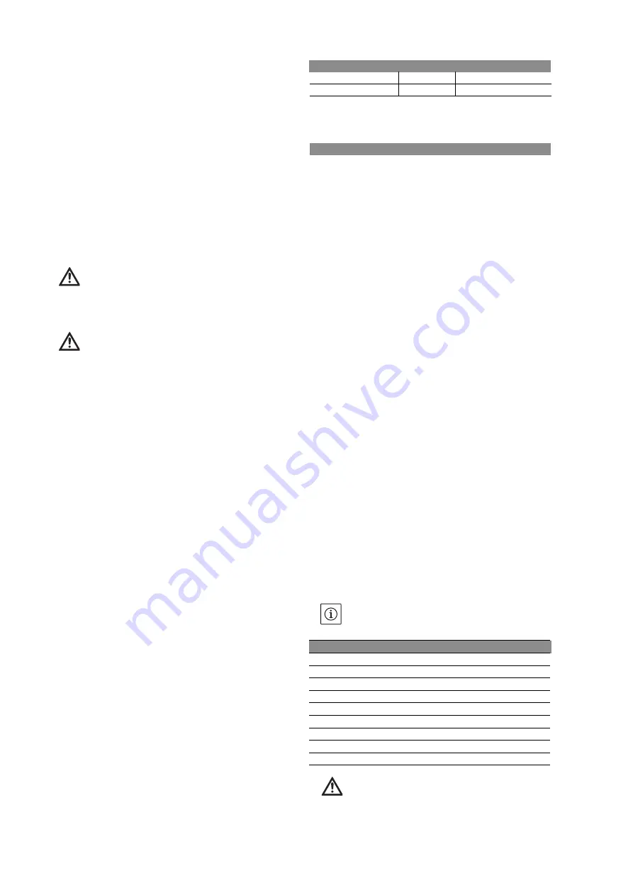
Maximun number of starts per hour
4.4 Accessories (as option)
• By-pass kit • isolating valves • bladder or gal-
vanised tank • tank for antihammer blow effect •
control box • PN 25 weld-on counter-flange
(steel) or tapped (stainless steel) • tapped oval
counter-flange PN 16 in stainless steel - motor
overload release • non-return valves • strainer-
foot valve • vibrationless sleeves • dry-running
protection kit • flexible collar type Victaulic style
77 • threaded muff joint (stainless steel)…
5. INSTALLATION
Two standard cases:
• fig. 1: pump in suction
• fig. 2: pump under pressure on storage tank (9) or
town water supply (10) with dry-running protection
system.
5.1 Montage
Install the pump in a place easy to reach,protect-
ed against frost and as close as possible from the
drawing point.
Install the pump on a concrete block (at least 10
cm high) (fig. 12) and fix with anchor bolts
(installation plan fig. 3).
Foresee an isolating material under the concrete
block (cork or reinforced rubber) to avoid any
noise and vibration transmission into the instal-
lation.
Before final tightening of anchor bolts, ensure
that the pump axis is vertical: use shims if neces-
sary.
Bear in mind that the altitude of the installation
place and water temperature may reduce the
suction head of the pump.
CAUTION !
When the conveyed fluid is above 80°C, plan to
install the pump under pressure.
Motor Power (kW)
0,37 0,55 0,75 1,1 1,5 1,85 2,2 2,5
Direct 100 90 75 60 50 45 40 40
FREQUENCY
50Hz
60Hz
Speed RPM
2900
3500
Winding* TRI
≤
4
230/400 V 220/380V to 254/440V
Altitude
Loss of head
Temperature
Loss of head
0 m
0 mCL
20 °C
0,20 mCL
500 m
0,60 mCL
30 °C
0,40 mCL
1000 m
1,15 mCL
40 °C
0,70 mCL
1500 m
1,70 mCL
50 °C
1,20 mCL
2000 m
2,20 mCL
60 °C
1,90 mCL
2500 m
2,65 mCL
70 °C
3,10 mCL
3000 m
3,20 mCL
80 °C
4,70 mCL
90 °C
7,10 mCL
100 °C
10,30 mCL


