


SCH & SCL
Oil Furnaces
–
Furnace Manual
4
670-000-006-1007
1
Prepare furnace location
(continued)
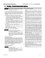
Vent pipe clearances
Table 2
Minimum clearances – side-wall venting
CLEARANCES
Vent pipe, up to vent terminal
3"
Vent terminal
Zero
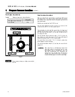
Figure 1
Do not enclose venting in a ceiling or combustible
structure.
Vent terminal location
Select a location for the vent terminal in accordance with all local
and national codes. The following requirements shall be considered
to be minimum requirements that can be overridden by stricter local
and national codes.
Following are excerpts from the NFPA 31 code:
The vent shall terminate at least 3 ft. above any air inlet to the
structure that is within 10 ft. of the termination point.
The combustion air inlet and flue gas outlet of a direct vent
appliance shall terminate at least 1 ft. (0.3 m) from the soffit of the
roof of the structure and at least 3 ft. (0.9 m) from an inside corner of
an L-shaped structure.
The vent terminal shall be located at least 1 ft. (0.3 m) from any
door, window or air inlet to the structure. The flue gas outlet terminal
shall also terminate at least 1 ft. (0.3 m) above grade.
The vent shall not be less than 7 ft. ( 2.1 m) above grade, when
located adjacent to public walkways.
The vent shall terminate at least 5 ft. (1.6 m) from the vent outlet of a
supply tank.
Most codes have a notwithstanding clause which
states that, products of combustion shall not enter
the dwelling under any circumstances, even if all
other code requirements as to construction and
location have been complied with. The installer is
ultimately responsible to do whatever is necessary
to ensure that flue gases do not enter the dwelling.
CAUTION
WARNING
Содержание SCH High Boy
Страница 12: ...SCH SCL Oil Furnaces Furnace Manual 12 670 000 006 1007...
Страница 13: ...SCH SCL Oil Furnaces Furnace Manual 670 000 006 1007 13...
Страница 14: ...SCH SCL Oil Furnaces Furnace Manual 14 670 000 006 1007...
Страница 25: ...SCH SCL Oil Furnaces Furnace Manual 670 000 006 1007 COMPONENTS AND REPLACEMENT PARTS 25...
Страница 39: ...SCH SCL Oil Furnaces Furnace Manual 670 000 006 1007 X40132 Rev D 39...