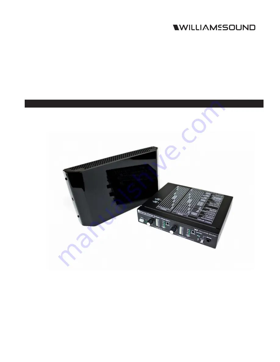
SoundPlus
®
Infrared Listening System
Installation Guide and User Manual
TX9 EMITTER
MOD 232 MODULATOR
MAN 132I
Страница 1: ...SoundPlus Infrared Listening System Installation Guide and User Manual TX9 EMITTER MOD 232 MODULATOR MAN 132I ...
Страница 2: ...tters Installed to Maximize Coverage 10 Compressor Gain 11 TX9 Features and Controls 12 Mounting the TX9 12 Receiver Safety Information 13 Recycling Instructions 13 Infrared Receivers 14 Trouble Shooting 15 TX9 Indicator Light Is Not On 15 Only TX9 s Power Indicator LED Comes On 15 No Sound Through Receivers 15 Sound Through The Receivers Is Weak And Noisy 15 Buzzing Or Humming Noise In Sound Syst...
Страница 3: ...uipment Infrared systems generally cannot be used in direct sunlight because of sunlight s large amount of interfering infrared light Note This equipment has been tested and found to comply with the limits for a Class A digital device pursuant to part 15 of the FCC Rules These limits are designed to provide reasonable protection against harmful interference when the equipment is operated in a comm...
Страница 4: ...RDING OR ROUTING PROCESSED AUDIO TO ANOTHER SOUND SYSTEM POWER IN 24 VAC 50 60Hz 120 VAC US TFP 016 POWER SUPPLY 230 VAC CE TFP 027 POWER SUPPLY CONFIGURATION SWITCHES CONTROLS CHANNEL SELECTION COMPRESSOR GAIN MIC LINE INPUT CHANNEL ON OFF AND OTHER CONTROLS BASEBAND INPUT A SECOND MODULATOR MAY BE CONNECTED HERE FOR 4 FOUR CHANNEL OPERATION WARNING POWERLINE VOLTAGE MUST NOT FALL BELOW 94V OR SY...
Страница 5: ...0m max length www william ssound com In Out Out 50 Ohms Baseband Modulation Mounting Bracket RoHS Class 1 LED Product Williams Sound Minneapolis Minnesota USA Patent Pending WIR TX9 EMITTER REAR Power On Baseband On Multi Channel Infrared Transmitter Made in U S A 24 VAC NC CAUTION RISK OF ELECTRIC SHOCK DO NOT OPEN WARNING TO REDUCE THE RISK OF FIRE OR ELECTRIC SHOCK DO NOT EXPOSE THIS EQUIPMENT ...
Страница 6: ...n BALANCED LINE USING 3 PIN CONNECTOR IN PHASE 1 2 3 3 PIN CONNECTOR A108 UNBALANCED LINE USING 3 PIN CONNECTOR 1 2 3 3 PIN CONNECTOR A105 BALANCED LINE USING 1 4 CONNECTOR IN PHASE A106 UNBALANCED LINE USING 1 4 CONNECTOR A107 Features and Controls Figure 6 Features and Controls MOD 232 Rear A254 COMPRESS CONTROL 2 1 SETTING WILL INCREASE TRANSMITTED AUDIO UP TO 30 dB DURING PERIODS OF LOW LEVEL ...
Страница 7: ... be set to different frequencies A250 Compressor Gain The MOD 232 s Compressor Gain is set in Moderate mode from the factory Use this setting for simultaneous interpretation Be sure that the compress control located on the front of the MOD 232 Figure 6 page 6 is turned fully counter clockwise Compression can be added if desired by turning the compress control clockwise For hearing assistance appli...
Страница 8: ...reasing the coverage area Rough surfaces tend to absorb infrared light minimizing reflections and limiting coverage to the direct illumination Remember opaque objects block infrared light Thus emitters cannot be concealed behind opaque walls curtains etc The emitter front red plastic lens must NOT be painted Neither should emitters be used in areas of extreme high or low temperature humidity or ch...
Страница 9: ...8 RECEIVER RX15 2 RECEIVER RECEIVER COVERAGE AREA WITH TX9 OR TX90 TRANSMITTER IN SINGLE CHANNEL MODE A136 These patterns are the direct radiation pattern The infrared radiation does not drop to zero outside the illustrated patterns it decreases It still may be usable at a greater distance depending on the receiver sensitivity and the reflective characteristics of the room Reflections of the infra...
Страница 10: ...h www williamssound com In Out Out 50 Ohms Baseband Modulation Mounting Bracket RoHS Class 1 LED Product Williams Sound Minneapolis Minnesota USA Patent Pending TO ADDITIONAL EMITTERS TO ADDITIONAL EMITTERS WIR TX9 EMITTER 2 REAR WIR TX9 EMITTER 1 REAR Power On Baseband On Multi Channel Infrared Transmitter Made in U S A 24 VAC NC CAUTION RISK OF ELECTRIC SHOCK DO NOT OPEN WARNING TO REDUCE THE RI...
Страница 11: ...the MOD 232 s Compressor Gain can be set to Maximum mode For additional compression use a tuning wand PLT 005 or small screw driver and gently turn the compress pot Figure 6 page 6 on the front of the MOD 232 clockwise The difference between Moderate and Maximum Compressor Gain is illustrated below Figure 14 A251 2 1 COMPRESSION RATIO MAX GAIN 2 1 COMPRESSION RATIO MODERATE GAIN 1 1 C O M P R E S ...
Страница 12: ...Cable RG58 Use RG58 Coax 1000 ft 350m max length www williamssound com In Out Out 50 Ohms Baseband Modulation Mounting Bracket RoHS Class 1 LED Product Williams Sound Minneapolis Minnesota USA Patent Pending A257 WALL CEILING MOUNTING BRACKET FOR USE WITH BKT 024 MOUNTING BRACKET POWER ON LED VISIBLE ON BOTTOM BASEBAND ON LED VISIBLE ON BOTTOM BASEBAND OUT BNC CONNECTOR 50Ω 50 kHz 8 MHz BASEBAND B...
Страница 13: ...e batteries which may explode release dangerous chemicals cause burns or other serious harm to the user or product MEDICAL DEVICE SAFETY CAUTION 1 Before using this product with an implantable or other medical device consult your physician or the manufacturer of your implantable or other medical device 2 If you have a pacemaker or other medical device make sure that you are using this product in a...
Страница 14: ... ON INDICATOR CHANNEL SELECTOR Channel Frequency 1 2 3 MHz 2 2 8 MHz 3 3 3 MHz 4 3 8 MHz Figure 14 WIR RX15 2 Headset Receiver INFRARED SENSOR BATTERY COVER POWER CHANNEL SWITCH POWER CHANNEL INDICATOR A169 AUDIO INPUT JACK MONITOR MUTE BUTTON VOLUME KNOB RIGHT LEFT MUTE Figure 15 WIR RX18 Under the chin Receiver BATTERY BAT AP11A A235 VOLUME CONTROL ...
Страница 15: ... Frequency Indicator should be lit and there should be activity on the MOD 232 Level Indicators Make sure the eye is not covered up on the receiver There must be clear line of sight between the receiver eye and the emitter panel Sound Through The Receivers Is Weak And Noisy Make sure each channel is set to a different frequency on the MOD 232 modulator Listen to the audio signal through the Phones...
Страница 16: ...ates frequency malfunctions Compress Control 1 1 or 2 0 1 Input Mix LED Indicates inputs A and B audio are mixed and transmitted by CHA CHB off Stereo LED Indicates stereo mode Phones Switch Selects CH1 or CH2 for phones when not in stereo mode Phones Output 1 4 TRS headphone jack Accepts stereo mono and any impedance phones Infrared Test LED IR LED for receiver testing monitoring and audio signal...
Страница 17: ...nel mode when using the RX22 4 Receiver 18 000 sq ft 1700 sq m in two channel mode when using the RX22 4 Receiver 11 000 sq ft 1000 sq m in four channel mode when using the RX22 4 Receiver 3 500 sq ft 325 sq m in single channel mode when using the RX15 2 Receiver 3 063 sq ft 285 sq m in single channel mode when using the RX18 Receiver See coverage area diagrams Baseband Input BNC 100 mV per carrie...
Страница 18: ...EMENT OF THE PRODUCT NO PERSON HAS ANY AUTHORITY TO BIND WILLIAMS SOUND TO ANY REPRESENTATION OR WARRANTY WITH RESPECT TO THE SOUNDPLUS INFRARED LISTENING SYSTEM UNAUTHORIZED REPAIRS OR MODIFICATIONS WILL VOID THE WARRANTY The exclusions and limitations set out above are not intended to and should not be construed so as to contravene mandatory provisions of applicable law If any part or term of th...
Страница 19: ...SoundPlus Infrared Listening System 19 This page has been left blank ...
Страница 20: ...20 SoundPlus Infrared Listening System 2019 Williams AV LLC MAN 132I info williamsav com www williamsav com 800 843 3544 INTL 1 952 943 2252 ...