


d
or
a
b
Wall cladding
Drywall screw Ø 3.9
Mask perforated
profiles before
mortaring
53
b
approx.
+
N
D
25
a
U frames
from Walls
profiles
Mineral wool filling
Fill on both sides
Drywall screws 3.9
Wall cladding
User Manual 5.12 (2019-09) 7
Subject to change
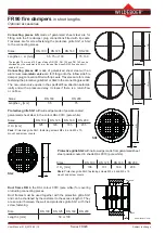
Series FR92K
Installation
opening a x b
or
∅
d
for mortar filling:
a
≥
DN
+
25
mm
b
≥
DN
+
50
mm
d
≥
DN
+
50
mm
Installation recommendation
•
Construct metal stud wall with an installation opening and apply cladding on the one side.
•
Fill installation opening with mineral wool and apply a second cladding.
•
Cut installation opening in claddings and mineral wool filling and chamfer them all around.
•
Insert and align fire damper.
•
Seal remaining joints with gypsum filler or equivalent.
All dimensions in mm
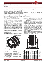
FR90 fire dampers
in short lengths
Installation in rigid walls and ceilings and in metal stud walls
Rigid walls and ceilings
can be made of concrete, lightweight concrete, porous
concrete (aerated concrete) or plaster. They can be a masonry or wallboard
construction and must have a bulk density of
≥
450
kg/m³. Walls may also be
configured as fire walls, shaft walls, shafts or ducts.
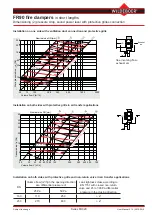
Required
minimum thicknesses
for installation of the fire damper
W,
D
[mm]:
Fire resistance period
in minutes
30
60
90
120
Rigid walls
100
Rigid ceilings
100
The
metal stud walls
must be clad with at least 2 layers of 12.5 mm DF gyp
-
sum boards according to EN 520. GKF gypsum boards, Fermacell boards or
other equivalents must be used. The metal stud distances (spans) can be up
to 1,000 mm. Profiles for metal stud walls are described in DIN
18182 and
EN
14195, constructions in DIN
18183.
Fire resistance period
in minutes
30
60
90
120
1)
Metal stud wall
95
1)
for installation with mineral wool
up to DN
200 only!
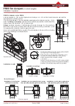
Installation
with mineral wool
Installation
with mortar
Installation
with mortar
Installation opening
The following is required in the wall claddings:
•
U frame a x b
≥
DN + approx. 50 mm
•
Installation opening
∅
= DN + approx. 6 mm
•
Notch = 35 x 25 mm and as follows
- on one side for a wall thickness of
≥
125 mm
- on both sides for a wall thickness < 125 mm.
The space around the enclosure of the fire
damper must be filled with
mineral wool
with a
bulk density of
≥
100 kg/m³ up to the U frame.
The dimensions of the installa
-
tion opening for mortar filling can
be as above for rigid walls.
Required
minimum thicknesses
W
for installation of the fire
damper
[mm]:


