background image

PRODUCT WARRANTY 

PW1

:LOEXU&XUWLV&R,QFFHUWL¿HVWKDWLWVSURGXFWVDUHIUHHIURPGHIHFWVLQPDWHULDODQGZRUNPDQVKLSXQGHUQRUPDOXVH7KHIROORZLQJOLPLWHG
ZDUUDQWLHVDQGFRQGLWLRQVDSSO\

3


years, parts and labor, from original date of purchase on digital control boards

2

\HDUVSDUWVIURPRULJLQDOGDWHRISXUFKDVHRQDOORWKHUHOHFWULFDOFRPSRQHQWV¿WWLQJVDQGWXELQJ

1

\HDUODERUIURPRULJLQDOGDWHRISXUFKDVHRQDOORWKHUHOHFWULFDOFRPSRQHQWV¿WWLQJVDQGWXELQJ

$GGLWLRQDOO\:LOEXU&XUWLV&R,QFZDUUDQWVLWVJULQGLQJEXUUVIRUIRUW\PRQWKVIURPWKHGDWHRISXUFKDVHRUSRXQGVRIFRIIHHZKLFKHYHU
FRPHV¿UVW6WDLQOHVVVWHHOFRPSRQHQWVDUHZDUUDQWHGIRUWZR\HDUVIURPWKHGDWHRISXUFKDVHDJDLQVWOHDNLQJRUSLWWLQJ5HSODFHPHQWSDUWV
DUHZDUUDQWHGIRUQLQHW\GD\VIURPWKHGDWHRISXUFKDVHRUIRUWKHUHPDLQGHURIWKHOLPLWHGZDUUDQW\SHULRGRIWKHHTXLSPHQWLQZKLFKWKH
FRPSRQHQWLVLQVWDOOHG

$OOLQZDUUDQW\VHUYLFHFDOOVPXVWKDYHSULRUDXWKRUL]DWLRQ)RUDXWKRUL]DWLRQFDOOWKH7HFKQLFDO6XSSRUW'HSDUWPHQWDW
$GGLWLRQDOFRQGLWLRQVPD\DSSO\*RWRZZZZLOEXUFXUWLVFRPWRYLHZWKHIXOOSURGXFWZDUUDQW\LQIRUPDWLRQ

CONDITIONS & EXCEPTIONS

7KHZDUUDQW\FRYHUVRULJLQDOHTXLSPHQWDWWLPHRISXUFKDVHRQO\:LOEXU&XUWLV&R,QFDVVXPHVQRUHVSRQVLELOLW\IRUVXEVWLWXWHUHSODFHPHQW
SDUWVLQVWDOOHGRQ&XUWLVHTXLSPHQWWKDWKDYHQRWEHHQSXUFKDVHGIURP:LOEXU&XUWLV&R,QF:LOEXU&XUWLV&R,QFZLOOQRWDFFHSWDQ\
UHVSRQVLELOLW\LIWKHIROORZLQJFRQGLWLRQVDUHQRWPHW7KHZDUUDQW\GRHVQRWFRYHU

• 

Adjustments and cleaning: 

The resetting of safety thermostats and circuit breakers, programming and temperature adjustments are the 

responsibility of the equipment owner. The owner is responsible for proper cleaning and regular maintenance of this equipment.

• 

Replacement of items subject to normal use and wear: 

This shall include, but is not limited to, spray heads, faucets, light bulbs, shear 

disks, “O” rings, gaskets, silicone tubing, silicone elbows, canister assemblies, whipper chambers and plates, mixing bowls, agitation 
assemblies and whipper propellers.

7KHZDUUDQW\LVYRLGXQGHUWKHIROORZLQJFLUFXPVWDQFHV

• 

Improper operation of equipment: 

The equipment must be used for its designed and intended purpose and function.

• 

Improper installation of equipment: 

This equipment must be installed by a professional technician and must comply with all local elec-

trical, mechanical and plumbing codes.

• Improper 

voltage: 

Equipment must be installed at the voltage stated on the serial plate supplied with this equipment.

• 

Improper water supply: 

7KLVLQFOXGHVEXWLVQRWOLPLWHGWRH[FHVVLYHRUORZZDWHUSUHVVXUHDQGLQDGHTXDWHRUÀXFWXDWLQJZDWHUÀRZUDWH

• 

Damaged in transit: 

Equipment damaged in transit is the responsibility of the freight company and a claim should be made with the carrier. 

• 

Abuse or neglect (including failure to periodically clean or remove lime accumulations): 

The manufacturer is not responsible for 

variation in equipment operation due to excessive lime or local water conditions. The equipment must be maintained according to the 
manufacturer’s recommendations.

Repairs and/or Replacements 

DUHVXEMHFWWR&XUWLV¶GHFLVLRQWKDWWKHZRUNPDQVKLSRUSDUWVZHUHIDXOW\DQGWKHGHIHFWVVKRZHGXSXQGHU

QRUPDOXVH$OOODERUVKDOOEHSHUIRUPHGGXULQJUHJXODUZRUNLQJKRXUV2YHUWLPHFKDUJHVDUHWKHUHVSRQVLELOLW\RIWKHRZQHU&KDUJHVLQFXUUHG
E\GHOD\VZDLWLQJWLPHRURSHUDWLQJUHVWULFWLRQVWKDWKLQGHUWKHVHUYLFHWHFKQLFLDQ¶VDELOLW\WRSHUIRUPVHUYLFHLVWKHUHVSRQVLELOLW\RIWKHRZQHURI
WKHHTXLSPHQW7KLVLQFOXGHVLQVWLWXWLRQDODQGFRUUHFWLRQDOIDFLOLWLHV:LOEXU&XUWLV&R,QFZLOODOORZXSWRPLOHVURXQGWULSSHULQZDUUDQW\
VHUYLFHFDOO

Return Merchandise Authorization (RMA):

$OOFODLPVXQGHUWKLVZDUUDQW\PXVWEHVXEPLWWHGWRWKH:LOEXU&XUWLV7HFKQLFDO6XSSRUW'HSDUWPHQW

SULRUWRSHUIRUPLQJDQ\UHSDLUZRUNRUUHWXUQRIWKLVHTXLSPHQWWRWKHIDFWRU\

All returned equipment must be properly re-packaged in the 

original carton and received by Curtis within 45 days following the issuance of a RMA.

1RXQLWVZLOOEHDFFHSWHGLIWKH\DUHGDPDJHGLQ

WUDQVLWGXHWRLPSURSHUSDFNDJLQJ

NO UNITS OR PARTS WILL BE ACCEPTED WITHOUT A RETURN MERCHANDISE AUTHORIZATION 

(RMA). THE RMA NUMBER MUST BE MARKED ON THE CARTON OR SHIPPING LABEL. All warranty claims must be submitted within 
60 days of service. Invoices will not be processed or accepted without a RMA number. Any defective parts must be returned in order 
for warranty invoices to be processed and approved.


$OOLQZDUUDQW\VHUYLFHFDOOVPXVWEHSHUIRUPHGE\DQDXWKRUL]HGVHUYLFHDJHQW&DOO

WKH:LOEXU&XUWLV7HFKQLFDO6XSSRUW'HSDUWPHQWWR¿QGDQDJHQWQHDU\RX

130%6$58"33"/5: ø

#

Содержание G4CBHS

Страница 1: ...READ AND SAVE THESE INSTRUCTIONS NOTICE TO INSTALLER Please leave this booklet with the machine G4 High Volume Combo Brewers 022317A FC3 G4CBHS G4CBHT FRONT COVER F 10002 revA USER S GUIDE...

Страница 2: ...3DUWV 5HFRPPHQGHG 3DUWV 7DQN VVHPEO 7ZLQ IP20 OHFWULFDO 6FKHPDWLF 6 ES7 OHFWULFDO 6FKHPDWLF 7 ES8 7URXEOHVKRRWLQJ XLGH 7 7URXEOHVKRRWLQJ XLGH 7 7URXEOHVKRRWLQJ XLGH 7 UURU RGHV EC1 3URGXFW DUUDQW 3 C...

Страница 3: ...LRQV 6HOHFWHG 0RGHOV OHFWULFDO 6XSSO 5HTXLUHPHQWV 02 6 5 37 21 3 6 92 76 036 7 1 21 5 776 57 5 6 Single Combo High Volume Brewer 1 PH 110 220 V 15 0 12 7 A 2 X 1600 W 2W 3W G 1800 2800 W 50 60 Hz 12 0...

Страница 4: ...G Make sure that this brewer is installed and grounded according to the INSTALLATION INSTRUCTIONS CZ RVBMJmFE QFSTPOOFM CFGPSF BUUFNQUJOH UP VTF JU BJMVSF UP GPMMPX UIF 45 5 0 4536 5 0 4 could result...

Страница 5: ...PECIFICATIONS section for the correct size The water line should also be capable of being DPOUSPMMFE CZ B TIVU PGG WBMWF P OPU DPOOFDU UIF XBUFS MJOF UP B TBEEMF WBMWF 4 OUFSOBUJPOBM SFRVJSFT UIF GPMM...

Страница 6: ...ting power cable from the terminal block and remove 7 Feed the 220 Volt power cable into the brewer 8 On dual voltage units being operated at 220 Volts disconnect and cap the jumper wire between the C...

Страница 7: ...and the electrical TQFDJmDBUJPOT UIF XBUFS UBOL UZQJDBMMZ SFRVJSFT UP minutes to reach the factory set operating temperature When the water has heated Ready to brew will be displayed on the LCD scree...

Страница 8: ...FS PO UIF appropriate brew icon As soon as you hear the click of the brew valve lift your mOHFS SFXJOH XJMM CFHJO The brewer will brew coffee or tea based on the settings programmed into the universal...

Страница 9: ...brush for hard to clean areas Rinse with clean water then dry 3 Wipe the spray head area with a cloth soaked in a mild detergent solution Rinse with a cloth soaked with clean water removing any resid...

Страница 10: ...at cup for wear Replace the seat cup if it is damaged Clean the faucet parts with the detergent solution To avoid damage DO NOT use a brush to clean the faucet or the inside of the dispenser shank out...

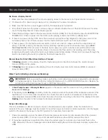
Страница 11: ...ording to the directions on the package 5 Air Dry Turn the container upside down and allow to air dry Cleaning the Faucet Parts Lid and Drip Tray Disassemble the faucet Unscrew the faucet assembly fro...

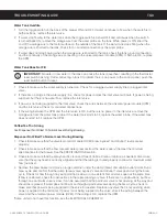
Страница 12: ...U QBTT DPEF JT 0ODF UIF DPEF JT FOUFSFE QSFTT 0 5IF 6 TDSFFO XJMM appear The access code can be reset in the POUSPM 4FUUJOHT TVC NFOV VOEFS 1BTTXPSET Status lights Brew Buttons Curtis logo Home Undo S...

Страница 13: ...d Gray Standard Amber Tropical Purple Tropical Gray 76 308 Purple 76 308 Gray Temperature Quality Timer Energy Savings Sounds Diagnostics Display Settings Preventative Maintenance Brew Counter Passwor...

Страница 14: ...M VQMPBE BMM PG UIF TFUVQ EBUB POUP UIF nBTI ESJWF 5IF ZFMMPX JDPO PO UIF UPQ MFGU PG UIF UPVDITDSFFO XJMM MJHIU JOEJDBUJOH UIBU EBUB JT USBOTGFSSJOH 5IJT QSPDFTT XJMM POMZ UBLF B TFDPOE UP DPNQMFUF D...

Страница 15: ...3 cm 61 7 cm 24 31 in 58 4 cm 22 99 in 1 29 in 23 65 in 60 1 cm 5 43 in 13 8 cm 45 7 cm 18 00 in 93 2 cm 36 71 in 85 7 cm 33 74 in 23 59 in 59 9 cm 20 84 in 52 9 cm 3 3 cm 58 0 cm 22 82 in 58 9 cm 23...

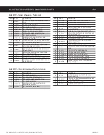
Страница 16: ...D PARTS RECOMMENDED PARTS 090616NC Supplies and Accessories All Models CAB 1 Cleaning Brush WC 29050 Spray Head Sold by the case 13 12 11 2 14 1 8 25 18 17 6 3 29 16 28 15 20 22 23 30 24 5 7 10 9 21 2...

Страница 17: ...8 WC 844 101 VALVE BY PASS NON ADJUSTABLE WITH RESTRICTOR WC 2945 10 WC 37255 KIT DUAL VALVE WATER INLET G4CBHS Recommended Parts to Stock ITEM PART DESCRIPTION 16 WC 13463 102 HARNESS ASSY COMPLETE...

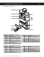
Страница 18: ...COMMENDED PARTS IP3 G4CBHS G4CBHT ILLUSTRATED PARTS RECOMMENDED PARTS 090616NC 1 13 25 5 3 8 12 17 11 6 22 27 15 2 14 28 20 18 31 16 4 33 7 19 10 26 21 9 29 30 23 32 24 G4CBHT Main Chassis Exploded Vi...

Страница 19: ...NG PLASTIC 6 WC 29050 SPRAYHEAD AMBER ADVANCED FLOW 7 WC 37122 KIT DUMP VALVE RIGHT 8 WC 844 101 VALVE BY PASS NON ADJUSTABLE WITH RESTRICTOR WC 2945 10 WC 37255 KIT DUAL VALVE WATER INLET ITEM PART D...

Страница 20: ...NG 1 6KW120V W JAM NUT SILICONE O RING 6 WC 1438 101 SENSOR TEMPERATURE TANK 8 WC 522 THERMOSTAT HI LIMIT HEATER CONTROL DPST 277V 40A WC 62080 Recommended Parts to Stock ITEM PART DESCRIPTION 9 WC 37...

Страница 21: ...PROBE WATER LEVEL O RING NUT 5 WC 934 04 KIT ELEMENT HEATING 2 5KW 220V W JAM NUT SILICONE WASHERS 6 WC 1438 101 SENSOR TEMPERATURE TANK WC 62033 Recommended Parts to Stock ITEM PART DESCRIPTION 8 WC...

Страница 22: ...Data_Communication First 12 Grinder Interlock 13 Solid State Relay Common 14 UPM Ground 1 TX Transmit 2 RX Receive 3 Not Used 4 Vdd 5Vdc 5 Vss Logic_Common r o t c e n n o C n i P 4 1 r o t c e n n o...

Страница 23: ...Used 10 Not Used 11 Not Used 12 Not Used 13 Dilution Right 14 Dilution Left 15 Bypass Valve Right 16 Bypass Valve Left 17 Not Used 18 Not Used 19 Current Sensor 20 Current Sensor 1 12 Vac Input Back L...

Страница 24: ...UIF WBMWF VTJOH UIF EJBHOPTUJDT JO TFDUJPO 5 Water Not Hot Enough G UIF XBUFS IFBUT CVU JT OPU IPU FOPVHI mSTU DIFDL GPS UIF DPSSFDU UFNQFSBUVSF TFUUJOH PO UIF DPOUSPM QBOFM 3FQSPHSBN BT OFDFTTBSZ 2 G...

Страница 25: ...F EJTQMBZ DIFDL GPS GBVMUZ XJSJOH BOE DPOOFDUJPOT CFUXFFO UIF VOJWFSTBM QPXFS NPEVMF 61 BOE UIF WBMWFT 2 G Brewing EPFT OPU BQQFBS PO UIF EJTQMBZ DIFDL GPS B GBVMUZ VOJWFSTBM DPOUSPM NPEVMF 6 PS VOJWF...

Страница 26: ...Filled To Normal Level During Brewing IFDL UP NBLF TVSF UIBU UIF VOJWFSTBM DPOUSPM NPEVMF 6 CSFX CZQBTT BOE EJMVUJPO MFWFMT BSF TFU QSPQFSMZ 2 IFDL UP NBLF TVSF UIBU UIF nPX SBUF BOE XBUFS QSFTTVSF G...

Страница 27: ...TFDUJPO GPS UIF NBYJNVN UJNFT BMMPXFE 0ODF UIF NBMGVODUJPO JT DPSSFDUFE UIF FSSPS NFTTBHF NVTU CF DMFBSFE 5P SFTFU UIF VOJU BOE SFUVSO UP OPSNBM PQFSBUJPO UVSO UIF UPHHMF TXJUDI PO UIF CBDL PG UIF CS...

Страница 28: ...F TFOPS JT BUUBDIFE UJHIUMZ to the tank and that heat sink compound was used A properly mounted sensor should have a resistance of around 7 k when the water is hot If not replace the sensor 3 Check to...

Страница 29: ...FTT Diagnostics 8IFO QSPNQUFE QMBDF BO FNQUZ DPOUBJOFS VOEFS UIF CSFX CBTLFU UIFO QSFTT OK 1SFTT B CVUUPO UP UFTU UIF EFTJSFE DJSDVJU PS Auto Test to test all circuits If a button is highlighted green...

Страница 30: ...e a mismatch in their settings 830 8 0 KDYH D PLVPDWFK LQ WKHLU VHWWLQJV UPZDUH XSGDWH needed Error Messages Brewer Will Stop Brewing MESSAGE DISPLAY ERROR DESCRIPTION CAUSE Water Level Error LOO UXQ...

Страница 31: ...per installation of equipment This equipment must be installed by a professional technician and must comply with all local elec trical mechanical and plumbing codes Improper voltage Equipment must be...

Отзывы: