background image

Operating Instructions Temperature Indicating Controller CF1M


V1.

1


03/200

5


- 21 -

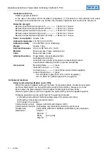
Heater burnout alarm [Option code: W1X]

Watches the heater current with CT (current transformer), and detects the burnout.
This option cannot be applied to the type current output.
When the option [SV2] or [CR5] is applied, the option [W1X] cannot be applied together.
Rating

: 5A [Option W10], 10A [Option W11],

20A [Option W12] or 50A [Option W15]

Setting range

: In the case of 5A, 0.0 to 5.0A   

(off when set to 0.0)

In the case of 10A, 0.0 to 10.0A (off when set to 0.0)
In the case of 20A, 0.0 to 20.0A (off when set to 0.0)
In the case of 50A, 0.0 to 50.0A (off when set to 0.0)

Setting accuracy: ±5%
Input resolution : 1/200 of each rated value
Action

: ON/OFF action

Output

: Open collector

Control capacity, 24Vdc 0.1A (maximum)

Setting value memory (external selection) [Option code: SV2]

If this option is applied, the main setting value 1 or 2 can be changed by the external contact.
When the option [W1X] or [CR5] is applied, the option [SV2] cannot be added together.
When the contact open : Main setting 1
When the contact closed : Main setting 2

Terminal cover [Option code: KAB]

Electrical shock protecting terminal cover

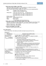
9. Troubleshooting

When troubled, refer to the following items after checking the power and the wiring.

<Indication>

Phenomenon

Presumed cause and the action

If PV/SV display is
indicating [

]

• Control output OFF function is working.
         Press the 

OUT

/

OFF

 key for approx. 1s to release the function.

If [

] is blinking

on the PV/SV display

• Thermocouple or RTD is burnt out.
   [In the case of Thermocouple]

If the input terminal of the instrument is connected,
and if nearby room temperature is indicated, the instrument
should be normal and sensor may be burnout.

   [In the case of RTD]

If approx. 100

 of resistance is connected to the input terminal

between A-B of the instrument and between B-B is connected,
and if nearby 0°C (32°F) is indicated, the instrument should
be normal and sensor may be burnout.

• Lead wire of thermocouple or RTD is not surely mounted to the

instrument terminal.

If [

] is blinking

on the PV/SV display

• Polarity of thermocouple or compensating lead wire is reverse.
• Codes (A, B, B) of RTD does not agree with the instrument terminal.

If indication of
PV/SV display is
abnormal or unstable.

• Designation of the Sensor input is improper.
• Temperature unit (°C or °F) is mistaken.
• Sensor correcting value is unsuitable.
        Set the value suitably.
• Specification of the Thermocouple or RTD is improper.
• AC leaks into thermocouple or RTD circuit.
• There is a piece of equipment to send out inductive interference

or noise near the controller.

Содержание Obsolete CF1M

Страница 1: ...xander Wiegand Straße 30 63911 Klingenberg Germany Phone 49 93 72 132 0 Fax 49 93 72 132 406 E Mail info wika de www wika de Temperature Indicating Controller Model CF1M WIKA Operating Instructions CF1M V1 1 03 2005 Operating Instructions ...

Страница 2: ...rm output open collector R Relay S Logic level DC 0 12 V for solid state relay Control output A Analogue current signal 4 20 mA Input M Multi function input input configuration setable H AC 100 240 V 50 60 Hz Power supply L AC DC 24 V B Factory adjustment Instrument configuration To customers specification CR5 Serial communication RS 485 W10 Heater burnout alarm for 1 phase max 5 A W11 Heater burn...

Страница 3: ...ting value MV is being displayed 5 Control output The green LED lights up when the control output is ON indicator 6 Event output The red LED lights up when the Temperature alarm Loop break alarm or indicator Heater burnout alarm is ON 7 Auto tuning The red LED blinks while the Auto tuning or Auto reset is being performed action indicator 3 Operation PV SV display indicates the characters of the se...

Страница 4: ...put low limit setting Proportional cycle setting Sensor correction setting Output ON OFF hysteresis setting Temperature alarm setting Instrument number setting Event output function selection Heater burnout alarm output setting Transfer rate setting Temperature alarm action selection Loop break alarm time setting Temperature alarm energized deenergized selection Loop break alarm action span settin...

Страница 5: ...alue to 0 disables the function With PD action I 0 auto reset can be performed 0 to 3600 seconds 200s Derivative time setting Sets the derivative time of control output Setting the value to 0 disables the function 0 to 3600 seconds 50s Proportional cycle setting Sets the proportional cycle value This setting item is not available when ON OFF action or current output type is selected 1 to 120 secon...

Страница 6: ...an Low limit alarm w standby Input range span to input range span 199 9 to input range span High Low limits w standby 0 to input range span 0 0 to input range span Hi Lo limit range w standby 0 to input range span 0 0 to input range span Process high alarm with standby Input range minimum to input range maximum Input range minimum to input range maximum Process low alarm with standby Input range m...

Страница 7: ...osen from 5 types of thermocouple and 4 types of RTD Multi range input type K 0 to 1370 C J 0 to 1000 C PL 0 to 1390 C N 0 to 1300 C E 0 to 800 C Pt100 199 9 to 850 0 C JPt100 199 9 to 500 0 C Pt100 200 to 850 C JPt100 200 to 500 C K 0 to 2500 F J 0 to 1800 F PL 0 to 2500 F N 0 to 2300 F E 0 to 1500 F Pt100 199 9 to 999 9 F JPt100 199 9 to 900 0 F Pt100 300 to 1500 F JPt100 300 to 900 F K PV filte...

Страница 8: ... item is not available if Temperature alarm output is not selected in Event output function selection nor if No alarm is selected in Temperature alarm action selection Energized Deenergized Energized Temperature alarm hysteresis setting Sets hysteresis value for temperature alarm This setting item is not available if Temperature alarm output is not selected in Event output function selection nor i...

Страница 9: ...ting value has reached 0 or output low limit value if the process variable PV has not fallen at least as low as the value of the span within the time it takes to assess the loop break alarm the alarm will also be activated When the control action is Direct Cooling the alarm acts conversely Energized Deenergized When the status of temperature alarm action is selected energized event output between ...

Страница 10: ...sor is indicated on the PV SV display Refer to table 3 1 1 and 3 1 2 During this time all outputs and LED indicators are in their OFF status After that the PV SV display indicates actual temperature If SV display is selected in PV SV display change the setting value will be indicated In the status the Control output OFF function is working it indicates on the PV SV display 2 Input the setting valu...

Страница 11: ...6 Action explanations 6 1 Standard action drawing Non contact voltage output Indicator OUT Green ON OFF ON OFF 12Vdc Heating reverse action Cooling direct action Proportional band Proportional band Action Setting Setting Cycle action according to deviation Changes continuously according to deviation Control action Current output Lit Unlit Unlit Lit part Acts ON or OFF Relay contact output 12 0Vdc ...

Страница 12: ...dicator OUT Green Current output Lit Unlit Lit Unlit part Acts ON or OFF Non contact voltage output Relay contact output Setting Control action Action Heating reverse action Cooling direct action Hysteresis Hysteresis Setting 12Vdc 4mAdc 0Vdc 20mAdc 12Vdc 0Vdc 4mAdc 20mAdc 4 3 3 3 3 3 3 4 4 4 4 4 4 3 3 4 3 4 3 4 4 4 3 3 ...

Страница 13: ...tor Output Indicator Lit Lit Lit Unlit Unlit Unlit Unlit Lit Alarm action Alarm action Unlit Process low alarm action High limit alarm with standby High Low limits alarm with standby part Acts ON or OFF part The standby functions 11 12 12 11 11 12 11 12 11 12 11 12 11 12 12 11 11 12 12 11 12 11 11 12 11 12 11 12 11 12 12 11 12 11 11 12 11 12 11 12 11 12 ON OFF ON OFF ON OFF Alarm action Output Ind...

Страница 14: ...the setting value h When the control is stable Fluctuation is given at the setting value ON OFF Unlit Lit Setting Small Large Load current 11 12 11 12 Temperature AT AT Auto tuning starting point PID parameter measuring PID parameter calculated point Controlling action is performed with the parameters set by auto tuning Setting value Time 1 2 3 3 2 1 Temperature 20 lower than the setting value F C...

Страница 15: ...that does not change suddenly 4 An ambient non condensing humidity of 35 to 85 RH or less 5 The controller away from large capacity electromagnetic switches or cables through which large current is flowing 6 No water oil or chemicals or where the vapors of these substances can come into direct contact with the unit 8 2 External dimension drawing Fig 8 2 1 Packing B Mounting frame Terminal cover 48...

Страница 16: ...CT current transformer dimension drawing CTL 6 S 5A 10A 20A CTL 12 S36 10L1 50A 8 5 Mounting Mounting panel thickness is from 1 to 10mm Insert the CF1M from the front of the panel Insert the mounting frame as shown in Fig 8 5 1 until the four tips of the frame touch the front panel Fig 8 5 1 60 40 45 0 6 0 22 2 0 3 0 ...

Страница 17: ...s of this controller Use a 3 wire system of RTD according to the input specifications of this controller This controller has no built in power switch nor fuse It is necessary to install them manually IEC approved 100Vac 5A 220Vac 5A in the circuit near the external controller In the case of 24Vdc do not confuse the polarity With the relay contact output type use an external auxiliary electromagnet...

Страница 18: ...aling range K 0 to 1370 C 0 to 2500 F J 0 to 1000 C 0 to 1800 F E 0 to 800 C 0 to 1500 F PL 0 to 1390 C 0 to 2500 F N 0 to 1300 C 0 to 2300 F Pt100 199 9 to 850 0 C 199 9 to 999 9 F 200 to 850 C 300 to 1500 F JPt100 199 9 to 500 0 C 199 9 to 900 0 F 200 to 500 C 300 to 900 F Input sampling period 0 25 seconds Input Thermocouple K J E PL N External resistance 100 Ω or less When input burnout Upscal...

Страница 19: ...e does not change at a rate higher than the setting span within the setting time Detects Heater burnout Sensor burnout and Abnormality at operation end Output Open collector Control capacity 24Vdc 0 1A maximum Control action PID action with auto tuning function PD action with auto reset function When I value is set to 0 P action with auto reset function When I and D values are set to 0 ON OFF acti...

Страница 20: ... cold junction temperature compensating function Input burnout indicating function upscale downscale Accessories Mounting frame 1 piece Instruction manual 1 copy Terminal cover 1 piece When option KAB is applied Current transformer 1 piece CTL 6 S When option W10 W11 or W12 is applied CTL 12 S36 10L1 When option W15 is applied 8 2 Optional functions Serial communication Option code CR5 When this o...

Страница 21: ...led refer to the following items after checking the power and the wiring Indication Phenomenon Presumed cause and the action If PV SV display is indicating Control output OFF function is working Press the OUT OFF key for approx 1s to release the function If is blinking on the PV SV display Thermocouple or RTD is burnt out In the case of Thermocouple If the input terminal of the instrument is conne...

Страница 22: ... may be set at the point the value does not change Set it again by Auxiliary function setting mode 1 Control Phenomenon Presumed cause and the action If process variable temperature does not rise Thermocouple or RTD is burnt out Lead wire of thermocouple or RTD is not securely mounted to the instrument terminal confirm the connection of the output is securely carried out If the main output remains...

Отзывы: